

Introduction: Solar Charged Battery Powered Arduino Uno


This instructable shows how to create a time switching battery powered solar charged circuit, which is used to power an Arduino Uno and some peripherals (sensors, communication modules, etc.).
If you want to design a remote data logger, power supply is always a problem. Most of the times there is no power outlet available, and that forces you to use some batteries to power your circuit. But eventually your device will go out of batteries... and you don't want to go there and charge it, right? So a solar charging circuit was proposed to user free energy from the sun to charge the batteries and to power your beloved Arduino.
Another problem your are going to face is the efficiency of your Arduino. It will consume a lot for your batteries, even if you put it to sleep. As described in Arduino's website (http://playground.arduino.cc/Learning/ArduinoSleepCode) "sleep is commonly used to save power on Arduino boards. For some Arduino variants, however, there is not much benefit. For example, the Arduino serial and USB boards use a 7805 type of power regulator, which needs 10 mA when the Atmega IC is in idle mode. Putting these boards to sleep will cut a few mA off the total power consumption however it will still be high".
If you bypass the inefficient regulator with your own power supply circuit, or use a board with a fairly efficient power supply, such as an Arduino Pro, then sleep can be very beneficial for reducing power and extending battery life. The regulator can even be removed altogether when using some Li-ion batteries.
But most of the times, you don't want to use your poor soldering skills directly on your Arduino Uno, or don't want to buy a more energy efficient device. If this is your case, this instructable is for you.
Another issue is that even if your Arduino is sleeping, your sensor might still be active, draining your batteries. So a timer circuit was added to the solar charged battery, which powers the Arduino only for a few seconds and then turns it off again to save power. It fits applications where your microcontroller is only used to read some sensors, transmit or save the data, and go back to sleep for a few minutes.
The circuit described here is still under test, a thorough analysis of the components used was not carried out (models diodes, transistors and resistor values). I intend to turn this circuit into a battery powered solar charging shield for Arduino Uno later, but for now I'm still on try and error fase. So, feel free to comment and to follow this project, and use it at your own risk!
I designed this circuit to power my Arduino mini-weather station ( https://www.instructables.com/id/Arduino-UNO-Mini-...). It uses a dust sensor that consumes a lot of power, and I wanted to turn off the whole circuit periodically to save my batteries.
Step 1:
Step 2: Materials


You'll need the following components for the construction of this solar powered circuit:
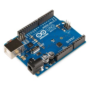
- Arduino Uno (buy)
- Small breadboard (buy)
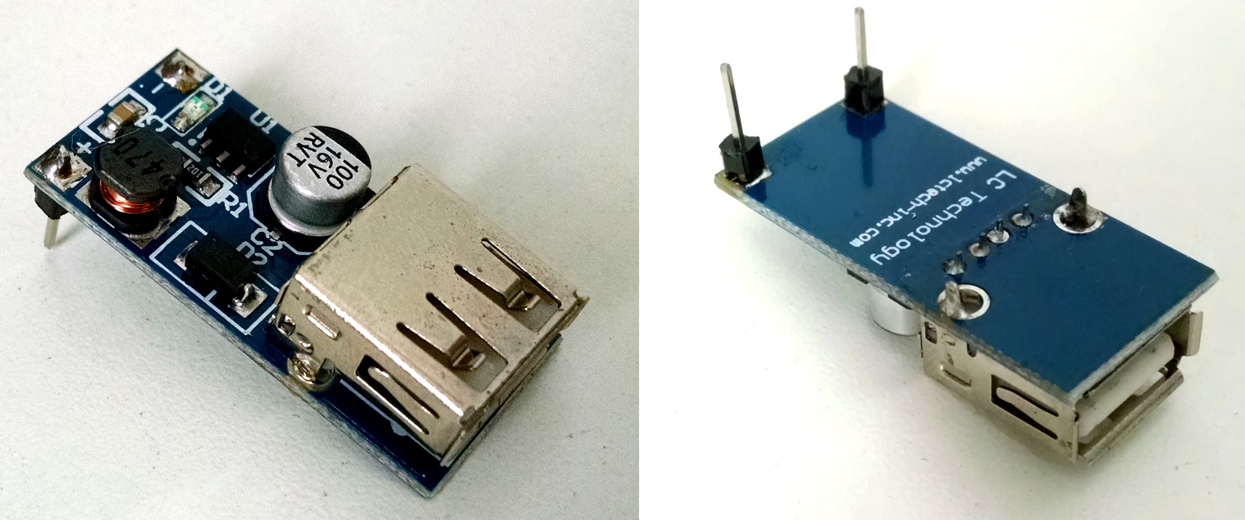
- 5V Step-up booster
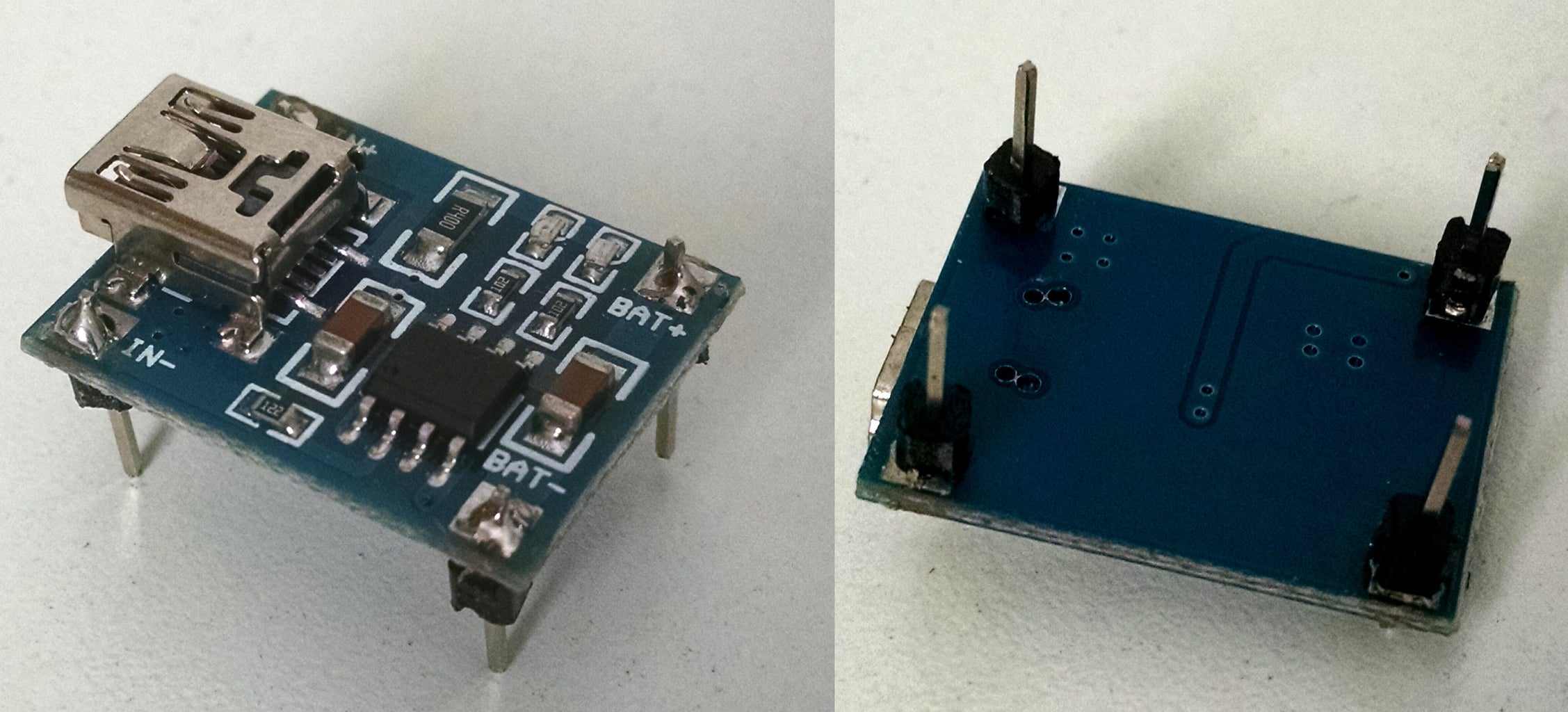
- Lithium battery charger (TP4056) (buy)
- 6V solar cell (buy)
- 18650 lithium battery (buy)
- Battery holder (buy)
- 1N4004 diode (x2)
- 555 integrated circuit
- 2N3904 transistor (x2)
- 1 Mohm resistor (x2)
- 100 kohm resistor (x3)
- 10 kohm resistor (x1)
- 100 uF electrolictic capacitor (x2)
- 10 nF ceramic capacitor (x1)
- 5V SPDT relay
- jumper wires
- USB cable
Step 3: Assembling Solar Powered Battery Charger

First you'll have to assemble the solar powered battery charger circuit. This uses the energy from some solar cells to charge the batteries, and boosts the voltage from it to the 5V used by the Arduino Uno.
This circuit was based on the awesome tutorial by deba168, Solar powered Arduino weather station.
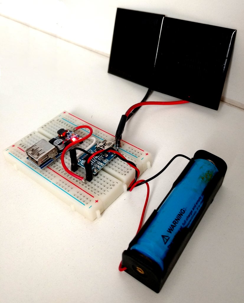
Solar cells are connected to the input of the lithium battery charger (TP4056), whose output is connected to the 18560 lithium battery. A 5V step-up voltage booster is also connected to the battery and is used to convert from 3.7V dc to 5V dc. You can check the connection between the components in the picture.
Some pins were soldered to the bottom of both modules (TP4056 and booster), to allow easier connection to a breadboard. If you don't to use a breadboard, you might connect the components with wires and solder them.
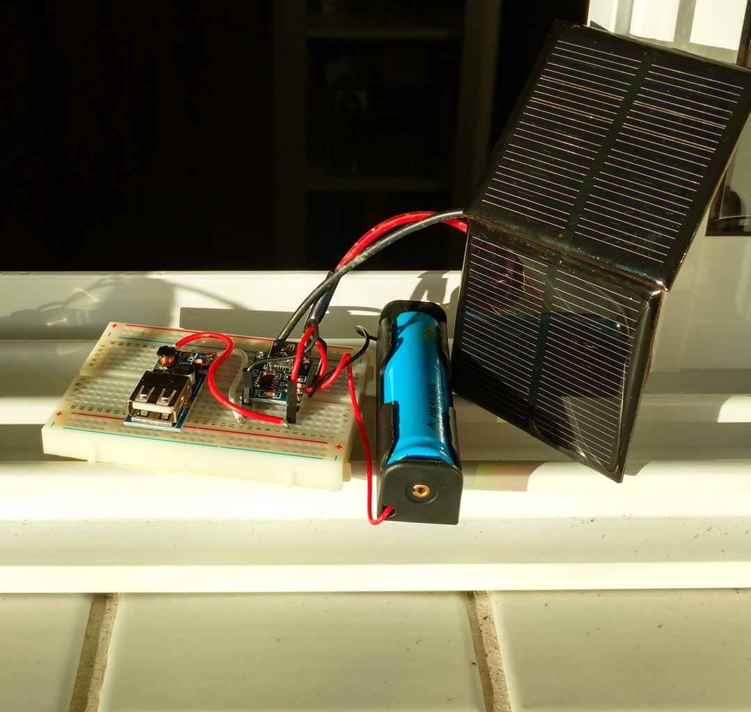
At this point you may already power your Arduino Uno, connecting it to booster's USB connector, and your Arduino will work until the battery is depleted. When there is enough sun light, the battery will automatically start to charge.
Notice that the TP4056 input is limited between 4.5 and 5.5V. I this circuit there is no voltage limiter between the solar panel and the battery charger. A Zener diode might be used limite the voltage and protect your circuit.
Depending on your power consumption, your battery will discharge quickly. If that's the case, follow to next step.
Step 4: Timer Circuit


There are lots of projects involving Arduinos and a bunch of sensors. In most of the cases the Arduino read the sensors periodically and store the readings internally or transmit their values using Wi-Fi, bluetooth, ethernet, etc... After that, it usually enters in an idle state until it reaches the next sempling time.
During this idle time, you may put you Arduino to sleep, but it won't save a lot of power. Although the microprocessor reduces its power consumption, the regulator and other peripherals (your sensors and communication modules, for instance) keep working, consuming most of the power.
The alternative proposed here is to use an external timer circuit, which switches the power on/off periodically. When it's on, the Arduino will perform its setup, read the sensor, and save or transmit the data. All of this in a few seconds. After that the circuit will cut the power for a few minutes and then restart the process.
During the off state the timer circuit consumes only a few miliamps.
The timer circuit was mounted on Autodesk Circuits (https://circuits.io/circuits/4588121-timer-1) so that it would be simulated before the implementation with real components.
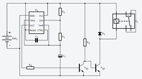
A 555 timer circuit in astable mode was designed to controll when the Arduino and its peripherals will be ON/OFF. In an astable circuit, the output voltage alternates between Vcc (+5V) (high state) and GND (0V) (low state) on a continual basis. This output was used to drive a relay, which will cut the Arduino's power periodically.
By selecting values for R1, R2 and C1, one can determine the period (the length of time it takes for the ON/OFF cycle to repeat), and the duty cycle (percentage of time the output is ON). Increasing C1 will increase the period. Increasing R1 will increase time high (T1), but will leave time low (T0) unaffected. Increasing R2 will increase time high (T1), increase time low (T0) and decrease the duty cycle.
Minimum duty for this kind of circuit is 50%. This means that, in the best scenario, the astable would cut the circuits power only half of the time, which was not enough. So it was decided to add a simple logical inverter (TQ1 and R4) at the output of the timer. This way the values of R1, R2 and C1 would be choosen so that the duty cycle was around 90% (before the logical inverter). After the inverter, output is ON for only 10% of the time. This inverted output is used to drive another transistor (TQ2), which is used to actuate a 5V relay (K1), which will finally cut the power of the Arduino and its peripherials.
Arbitrary values for resistors and capacitores were used in the first simulations, in order to verify the power consumption of the circuit. During the off state, the circuit indicate a consumption of only 0,8 mA. When the circuit is on (for a short time), it consumes around 40 mA, which is added to the current consumed by the Arduino (and other peripherals).
It's hard to measure the actual values, but the Arduino Uno usually consumes around 52 mA. When in sleep mode (using LowPower library), the consumption falls to 35 mA. New values for R1, R2 and C1 were calculated using a 555 Astable Circuit Calculator (http://www.ohmslawcalculator.com/555-astable-calcu...). Their values were choosen so that the circuit is off for 5 minutes, and then powered on for 27 seconds for sampling and transmitting data.
Considering those values (5 min OFF and 27 seconds ON), The Arduino with sleep mode would consume around 36 mAh. If we use the timer switching circuit, the consumption is only around 8 mAh. 77% reduction in power consumption seems good to me. You'll have also have to consider the current consumed by the rest of the electonics (sensor and communication modules), and voltage booster and battery charger in order to have a precise current value...
Step 5: Assembling Timer Circuit

Assemble the timer circuit according to the schematic.
The following values might be used for resistors and capacitor to achieve the 5 minutes off / 27 seconds on times:
R1 = 2 Mohms
R2 = 200 kohms
R4 = 10 kohms
R5 = 10 k ohms
C1 = 200 uF
C2 = 10 nF
It's important to notice too I used the normally open (NO) output of my SPDT relay. I realized that some relays only have a normally closed output, althought they have the same kind of package, and all the indications are the same.
Also notice that in the picture I use different values, because I didn't want to wait for 5 minutes to see my circuit working.
The picture shows the circuit mounted on a breadboard. I has one input (+5V/GND from voltage booster) and one output (+5V/GND to the Arduino).
Power the time circuit, with the Arduino connected to it, an see if it works. You listen the relay being actuaded from time to time.
Step 6: Complete Circuit and Testing
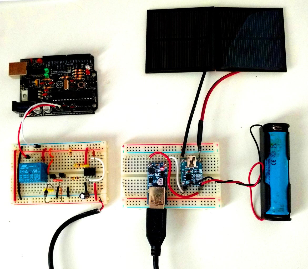
After the timer circuit is working, connect it output to Arduino 5V and GND pins. It will look like the one in the picture.
The Arduino will be powered every 5 minutes and stay on for 27 secons. You might change those values selecting differente values for the resistors and capacitores as described eartlier.
Design a nice case to protect your circuit, put it on the sun and see if it works!
Step 7: Power Consuption and Time of Operation
I'd like to make some considerations on the power consumption and time of operation.
Considering 5 min OFF and 27 seconds ON, the power consumption of the circuit + Arduino are the following:
Without switching circuit (using sleep mode):
Average currenge (Iavg) = (Ton*Ion + Toff*Ioff ) / (Ton +Toff)
Ton (Arduino is active) = 27 s
Ion = 51.7 mA
Toff (arduino off) = 5min = 300 s
Ioff = 34.9 mA
Iavg = 36.3 mA
Operating voltage (Vo) = 5V
Average power (Pavg) = Vo * Iavg = 5 * 36.3 = 181 mW
Li Ion battery capacity = 3000 mAh
Battery voltage = 3.7V
Power =3.7 * 3000 = 11100 mWh
Battery life = 11100/181 = 61 h = 2,5 days
With timer switching circuit:
Average currenge (Iavg) = (Ton*Ion + Toff*Ioff ) / (Ton +Toff)
Ton (arduino is active) = 27 s
Ion = 92 mA
Toff (arduino off) = 5min = 300 s
Ioff = 0.8 mA
Iavg = 8.2 mA
Operating voltage (Vo) = 5V
Average power (Pavg) = Vo * Iavg = 5 * 8.2 = 41 mW
Li Ion battery capacity = 3000 mAh
Battery voltage = 3.7V
Power =3.7 * 3000 = 11100 mWh
Battery life = 11100/41 = 270 h = 11 days
Power losses on the TP4056 and voltage booster were not considered here and will certailly decrease the battery life in both cases.
The important thing to notice here is that this timer circuit will save the some energy cutting the power of sensors as well, while the sleeping mode will onde reduce the consumption of the microprocessor.

Participated in the
Circuits Contest 2016

Participated in the
Solar Contest 2016

Participated in the
Survival Ready Contest


