

Introduction: Solar Powered Crystal Spinner - Simple, Brilliant Customisable LDR System, Custom Gearbox. Just Add Crystals (and Sun)


The more astute among you may have caught on already that rainbows are usually solar powered.
Solar Powered Rainbows
In this case solar powered rainbows is as simple as crystals + sun = Rainbows.


Ta daaaaah!
The rest of this Instructables will cover building...
A Solar Powered Crystal Spinner
Get your crystals spinning; throwing previously static rainbows all over your walls, floor, furniture and what not!

This device will be/have
- Solar Powered (scavenging and altering solar ornaments)
- Solar Triggered - because there isn't much point in spinning your crystals when there be no rainbows (however, my final version does include a switch to enter always spinning, always off and the default "spin when rainbow" mode)
- Slow speed (like single digit RPM)/ high torque rotating things on which to hang crystals (building your own gearbox - my debut into mechanical engineering)
This Instructables is rewritten in an effort to curb my enthusiasm and my word-count - it got ridic.
We will cover:
- Designing & building a gearbox optimized for low RPM and high torque (as pointed out in the comments by KipA2, you can purchase a low RPM high torque geared motor - with high reliability, and less noise. But building the gearbox is half the fun)
- Modifying a garden solar light to be capable of powering our motor
- Simple logic to initiate spinning crystals when appropriate (LDR system with MOSFET)
- Putting it all together in a box of sorts.
For those of you who just want to build it, each step will be summarized at the beginning of each step - the how, why and possibly the "Other things I tried first, if you can see how to achieve XYZ please share" sections will follow. Probably in that order.
Let's do this!
Supplies
To complete this Instructables in it's entirety, my way, you shall
Step 1: The Gearbox - Design (Play Time)


Summary
Small gear into big gear translates speed into torque. We want low speed and the added torque is a nice byproduct and will help reduce the load on our poor batteries later on.
Research has indicated that I'll want to go the worm gear route as it is less noisy, so stick that on your motor.
Play around with configurations by sticking gears on cardboard until you have a design you wish to make more permanent.
You want to step down the speed by a lot - these DC motors spin at several thousand RPM. This can be achieved by using these magnificent gears within/attached to larger gears.
When put together like this:

The speed is stepped down and your torque is increased in a space efficient manner
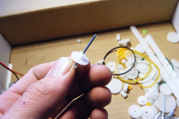
Here it is in action:

Then you will want to translate the gears rotation to the crystals by fixing (superglue) some gears to their spokes and letting the shafts rotate through the housing with crystals hanging from these shafts.
Your wish is your command. Let your desires shape your design. You have control of your crystals speed and rotational direction. Take the time to experiment it out. It's really easy and fun with the cardboard and pop rivets. Just push them in and give it a whirl (pun intended - no regrets).
My design
Stage 1 - Speed reduction/increased torque

Driving the center rotating gear instead of a side one seemed like a logical thing to do for getting an even distribution of stress.
Less stress = less noise, less likelyhood of gears jumping or other failure... I'm not a mechanical engineer, so this decision is driven purely by logic - correct me if best practices are otherwise.
From my worm gear, which is shoved on the motor, I go to a gear with a small gear within it/at it's center. We'll call this gear 1. The length of the shaft of the motor limits how large this first gear can be, because any bigger and it would be hitting the motor's chassis.
From there, I take 1's small gear to a big gear with a small gear which I'll call gear 2. and from there I take it to the final gear, gear 3. This completes the reduction stage. Gear 3's little inner gear meshes with gear 4, which leads me to Stage 2.
Stage 2 - The spinny ones (not that the others don't spin... but these ones serve solely to spin)

Basically gear 4 serves as my center crystal spinner. The spoke is attached to the gear with super glue so that the spoke too shall spin, and hanging therefrom shall be the center crystal.
Gear 4 has two smallish intermediary gears that basically serve to space out my crystals from one another a little, as the gears aren't really too big. These intermediary gears spin freely about their shaft. Honestly, you can do without these.
If you choose to mesh gear 4 directly with 5 and 6, then the outer two crystals would spin in opposing directions to the center crystal. While this was part of my original design intent, I wanted space between the crystals and wanted to eliminate unnecessary gears, but go nuts and be creative. I made my center gear larger than my outer ones so the large center crystal will spin slower than it's smaller counterparts.
Extra stuff
Here were some configurations I tried first:


Step 2: The Gearbox - Production Model


Hope you packed your patience, or an alternative technical solution (Perhaps a compass and straight edge with precision measurements and a steady hand - Still sounds like you'll be glad you packed that patience anyway)
Summary
Translate your cardboard design into something more permanent - like perspex.

Cut or Score and Snap a few slabs (you only need 1, but I cut a few in case I wanted a do over).
You may want to consider your final design now rather than later and cut these slabs to serve as your housing units base. Refer to this step on housing your device if you'd like.
I had best success drilling each gears hole after the previous gear's position was firmly established. I used my cardboard template first and that was wildly inaccurate (and upside down. a mistake I repeat later >__<) and there is little tolerance for error.
If your gears are placed too close together they will be inefficient at best and at worst jump away from the gears and don't mesh. If they are placed too far apart, they will be the most inefficient as they won't mesh at all with the gear before them, failing to spin and leaving you feeling like a dunce.
Not all is lost though, as long as your mistake hole is far enough away from your next drill attempt, you can just adapt your design and drill again. My final piece looked like swiss cheese. I conveniently didn't take a photo of it.
To elaborate: these gears being round and all, you can choose a new hole position by moving the next gear around the previous one instead of attempting to correct for same position.
From my limited experience, I'd recommend you rinse and repeat the following workflow until you are done:
- Place a gear in position with relation to it's previous gear
- Drill a hole for the shaft at it's center point (mark hole position with fineliner or something - drill through gear, at risk of damaging gear)
- Put gear on shaft
Use drill bits of exactly or very near the size of hole you need. This is again in the interests of gears meshing appropriately. You don't really want the shafts moving around (except the spinning ones obviously. Even then though, make your holes as near to the size of the shaft as possible without causing undue friction).
Specs of my gearbox at the bottom of this step.
My design
Using pop rivets had an unanticipated feature waiting to be exploited. They provided me with the perfect way to raise gears that needed raising, by drilling up the holes to fit the fat side and super gluing into position - as demonstrated in the image below:

Before discovering this technique I was using little plastic spacer pieces, which wasn't completely to my satisfaction.
Detailed specs of my gearbox: (I'm not counting the teeth. Your gear set will likely be similar to mine. And that is many teeth to count)


Motor:
- 3-6v DC brush motor (it runs off 1.5v though, and I intend to use it at 1.5v, because it spins slower and is less noisy)
Gears:
- Worm Gear - 5.9mm/0.23" diameter attached to motor shaft
- Gear 1 - 13.8mm/0.54" into 4.6mm/0.18" - Rotates freely with shaft static (Shaft raised to meet worm gear)
- Gear 2 - 19.7mm/0.77" into 4.7mm/0.18" - Rotates freely with shaft static (Shaft raised to meet gear 1)
- Gear 3 - 23.9mm/0.94" into 5mm/0.19" - Rotates freely with shaft static
- Gear 4 - 28.8mm/1.13" - Attached to shaft - Shaft extends through for attaching to crystal
- Intermediary gears (between 4 and 5 and between 4 and 6) - 16.7mm/0.69" - Rotates freely with shaft static
- Gear 5 and 6 - 24.8mm/0.97" - Fixed to shaft - Shaft extends through for attaching to crystal
- Pop rivets: Fat side of 3.2mm/0.12" with shaft of 1.7mm/0.06"
Step 3: Solar Powered Motor for Gearbox


Summary
Solar cells:
Produce voltage using light as an energy source. Connected in series, their voltage adds up. If you have 1v cells or something, hook up a few in series.
Batteries:
Hold this charge for use when you want it. The fact that we want it when it's available is inconsequential as the solar panel couldn't power the motor directly.
Charge Circuit:
Is responsible for managing how the batteries receive the energy supplied by the solar panel
You'll need all three to continue I think.
Mine was all scavanged from this with the batteries swapped out for larger ones.
You could always get an appropriate solar cell, a charging module and an appropriate battery solution from an electronics store that meets your demands (for my DC motor I needed to be able to deliver 1A at 2.4V to get it started).
Or you can work with what you've got on hand/in the garden. Cost effective and enlightening.
My Learnings
You'll need to drive that motor from something, and I originally thought I could do it straight off the solar panel. In short, you can't. In fact at the end of the day, and after all my trials and errors, it's possible all I ever needed was the battery upgrade.
Essentially, the solar panel had this circuit board with these AAA sized NiMh batteries. I had a breakthrough when I noticed the voltage drop to 0, which was the reason the motor would stop after a limited time.
The current demanded by my motor was too high for the batteries and they effectively shorted, with the motor acting as a low ohm resistor. This apparently causes irreparable damage to the batteries... This is discussed here.
We live and we learn.
I learned:
- You need to be able to deliver enough current (0.5A generally and somewhere just under 1A stall current - for my motor)
- At your running voltage (Mine is 2.4V - 2 x 1.2V batteries as stated on the battery label) to drive your motor without causing cataclysmic voltage drop.
You'll also want to protect everything that isn't your motor from your motor's reverse current. This happens when a motor stops being driven by electricity and thus temporarily becomes a generator. Use flyback diode. Refer to the step MOSFET as a switch on this page.
Also in the interests of protecting stuff is a capacitor. Motors are inherently messy, and this helps reduce their EMI and maybe helps your battery out...? *citation needed
If I were to mentally reverse engineer my setup and break it down for you, I'd say you want:
Solar Cells that provide above 3V to charge the batteries and a batteries/a battery that is equivalent or better than 2 x AA in series.
My Design
For me the solution came down to a simple battery swap. Refer to this video on soldering batteries to boards.
Out with the old 600mAh AAA size NiMh

And in with the new 2100mAh AA sized batteries.


Do they work? Yes.
Is there a voltage drop? ..... yes, but not a cataclysmic one. I'll take it.
Will these fancy new bigger batteries get charged by the original circuit? Time will tell. I can't see why not. Especially since I'm only planning on running it for a short period of time daily.
Step 4: Crystal Spinning Logic Control - When Sun, Make Spin


This is probably the most technical section for most laymen
Summary
When do you want them spinning? When they are receiving direct sunlight. Exactly.
Long story short, you can achieve this with an LDR driving a transistor. Light conditions will determine weather the transistor acts as closed or open. It's relatively simple using an N channel MOSFET and a trimpot to determine at what light level the LDR provides voltage rather then the trimpot, which is acting as a pull down resistor/voltage divider to regulate the voltage received by MOSFET.
![]()
Image curtosy of https://www.kitronik.co.uk/blog/how-an-ldr-light-dependent-resistor-works/ visit the link for more info.
My Design
... is a compromise to my initial ambitions. I'll rant on that after I go over current solution.
A more perfect example of "from the sublime to the ridiculous" I cannot imagine.
Sublime wasn't working, so ridiculous it must be.
Edit: Actually, I love the ridiculous version. It's so customizable and so simple. Sublime method wouldn't have been this good.
PRESENTING:
The unidirectional, mechanically programmable, hyperfocused Snail Eye LDR solution (SE-LDR for short). A potentially novel take on an otherwise commonplace circuit. * Play the gif if not auto playing

Ta daaaah!
Put your LDR and trimpot circuit (schematic above in Summary) on solid core wires using an open air circuit approach.

These wires will not only act as electron highways, but they shall serve too to assist with your mechanical programming.
Insulate using heatshrink.
Now give it a black hood of heat-shrink making this LDR hyper focused - much like blinkers on horses.

Trim that potentiometer so that only the brightest of light should register.
Now only from a specific angle will enough direct light happen across the LDR to signal the MOSFET to "close the circuit" and drive the motor, in turn spinning your crystals.
Which leads me to the mechanically programmable... Point at direction of sun for the time period you wish to have crystals spinning. Cut the hood shorter to loosen the focus if it's a little too picky. Trimming the hood will let in more light in general, and make it spin for longer. Keep in mind that the hyperfocus is intentional - spin them for only as long as your battery/solar panel situation can recharge.
Hood length and trimpot setting = duration.
Direction you physically point the SE-LDR in = the time, in accordance with the sun, who is this galaxy's real timekeeper anyway, that the crystals will spin
No clue what I'm talking about? - Don't worry about it. Here's a more detailed run down for those not yet into electronics. The what's, how's and why's that get your crystal spinner spinning when you want it to, automatically. If you are have some electronics knowledge, skim this and get the information you need or just check the schematics out.
First lets get familiar with what you've already got in front of you:
Basically, the solar panel applies voltage across at the S+ and S- parts, and the voltage from the batteries can be accessed by going from the positive pins to the S- part of the board.
I've labeled the important sections here:

- but yours may look different or act differently so...
Set your multimeter to read 20V DC. Read voltage across solar panel when it's in direct sunlight. Expect 3 to 4V
Next cover the solar panel and measure the voltage across the solar cell's points. The voltage should read somewhat low (under 1v). Now find somewhere to get positive voltage from batteries by leaving your black multimeter lead on the S- (which should be connected to the "global" ground) and probe potential spots with your red lead to find a voltage reading that adds up to about what your battery capacity is. Mine is 2x 1.2V batteries so I'm expecting to find a 2.4v reading somewhere. Make sure the point you chose is a decent point on which you can solder a wire. For me it was the pins near the negative terminal on the board.

Quick theory on MOSFETS:
MOSFETs are a type of transistor. We'll be using an N type MOSFET (as opposed to a P type) can be used as a "switch", by applying voltage to the gate (Pin 1) basically closing the circuit.
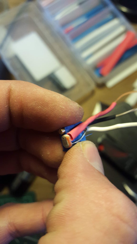
In practice, it looks like this - try it out: *NB CAVEAT BELOW
This was an old circuit for the "Sublime" solution but used in conjunction with this Fritzing, I'm sure you can put it together to continue with the SE-LDR:

NB THIS CAVEAT: This photograph was from the previously mentioned "sublime" design solution - it utilized the solar panel's voltage. The idea was that when the solar panel was in direct sunlight the MOSFET would take this input and allow the motor to spin from the battery source. It lacked control.
I think I see the error in my ways now after making the SE-LDR system. In hindsight it didn't lack control. I hadn't implemented it. I think the key would have been a 50k trimpot where that 10k resistor is. It's too late now for me. If you know, comment below. That is the rant I was having before my moment of enlightenment.
But back to the SE-LDR system that is currently the solution you are building if following along.
So we want to provide voltage to the gate of the MOSFET basically closing the circuit and powering the motor.
Apply voltage from another power source (eg 9v battery as seen in fritzing) to the MOSFET gate and watch your motor spin.
Cool. Now we are just going to send voltage through the following simple circuit first, using the LDR and a trimpot to only send voltage to the MOSFET under extremely bright conditions.
Now, take the LDR and trimpot, insulate these parts with small heatshrink or electrical tape. Leave the wires longish and use solid core wire so you can bend the eye into place.


Then put it in a large heatshrink hood, making sure you can still adjust the trimpot screw
Voila you have created the SE-LDR.
If, like me, you wish to be able to toggle between running the motor, not running the motor, and using the SE-LDR technology to control when the motor runs, we'll be adding a switch.
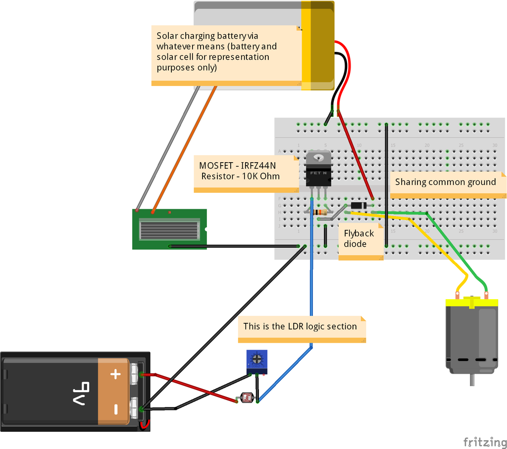
The complete circuit looks like this:

Breaking down that state switch for you. States from left to right:
- It will connect the LDR section to the centre pin, sending the LDR adjusted voltage to the MOSFET
- It connects nothing and through the resistor, the MOSFET will be pulled down to ground or 0V and will be "off"
- The voltage from the battery is sent straight to the MOSFET and it will be on, regardless of the LDR stuff of the first state.
Look at you go! From here on out it's plain sailing, I promise.
EDIT: AFTER about a week and a half my 9V battery has given up on life. It was already "dead" as far as alkaline batteries go but now it's no longer functional. I'd recommend either replacing it with something with more capacity (9V batteries are notoriously lousy). 2xAA rechargable batteries works perfectly. I've tried. with some slight modification you could also link them to the charge module to keep them tanked up. I'm swamped with work right now, but can update this Instructables accordingly when I have the time
Step 5: Housing Your Device


Here, dear reader I think you need little guidance.
Summary
Put it all in a box of some form or another. Solar panel on outside of course, and with the rotating shafts poking through. The rest is really up to you. I'll show you two design solutions I did. The quickfix and the prism of magic.
My Design
So if you want a quick fix: a cardboard box could do. My prototype faired well housed in a cardboard box while I struggled through the electronics situation.

Effective, cheap (free really) and quick. I poked holes in the appropriate places and planned to decorate the box after.
Kudos to my dad for designing/building the following housing:


Triangular prism because prisms go with rainbows like...*insert idiom here
Solar panel mounted on top/side to face sun, and everything else inside.
As discussed, I'm adding a switch for a hard "off", and an alternative hard "on" mode that bypasses the SE-LDR (mostly for testing/showing it off).
For ease, I redesigned it so that almost everything could be constructed onto the base.
Put it all together, pre-assembled on the base plate (save for the solar panel which is mounted on the "roof" and connects via the DC jack to the innards), slip assembly over the wooden housing, plug the solar panel into the perspex base using the DC jack and secure with something through the holes.
Edit: I've decided to make the roof from perspex too for uniformity in the look - choice is yours. It's your box.
Perspex pieces for my design:
Base - 200mm x 130mm, 7.87" x5.12"
Triangles - 87mm or 3,43" right angle isosceles triangles (basically a square with sides of that length cut from corner to corner)
*Sides - Can be made out of perspex too. When I have the appropriate tool's on hand, I'll be doing this.
Click here to return to the gearbox step.
I made a template again, but results were not fantastic (again I used template upside down first >___<). Template + enlarging holes + eyeballing works out. No real need for supreme accuracy here.
I sketched out my layout on the board before continuing and it looked a little something like this

Once satisfied and having checked tall things won't be bumping into the angled ceiling of the wooden enclosure, start sticking things down. Remember to feed the SE-LDR cables through the holes before soldering it up.
For my switch I've used a single pole double throw switch that is mounted into a round hole, because it's easier to drill round holes than square ones. You'll want the hole size to be appropriate for your switch to have a secure fit.
After soldering it all together, and securing elements with mounting tape, it may look something like this:

All that is left is to drill holes for the shafts and pop rivet bits and insert the gearbox.

Haaardy haar harrrr... Swiss cheese.
Well, lets see you do better. I'm serious, I want to see your one. I spent too much time on this Instructables for no one to make it.


Now Your motor will need to be at the right height... So I hacked up perfboard and stacked it accordingly with superglue between layers.


And super glue the motor to the perfboard.

I used multiple layers of mounting tape initially but it was noisier than fixing it securely.
Drill holes in your triangular bits before sticking them to the base, because it'll be easier before it's assembled.
Attach a male DC jack to your solar panel, being sure you have the polarity correct. Red is VCC and black is 0V/GND/Ground! VCC is also the small bit (pin on female and hole on male) and GND is the sheath.


Finally, stick the perspex elements together. Acetone melts and bonds the perspex onto the other perspex. It's effective, forgiving (takes a little longer to dry, so you can shift things around, unlike superglue sometimes) and simple. Secure everything and let it dry for a while.
Or if, like me you didn't ration your patience out properly between the steps, just use superglue. It's fast and effective.
CONGRATULATIONS! Your device is now suitable for end user assembly!
NB Acetone can be quite the substance, melting the unexpected etc. Including superglue. so don't acetone near superglue that you want to keep sticking, and work over newspaper or something.
Step 6: The Final Patience Trial

Wait for morning and enjoy ;)
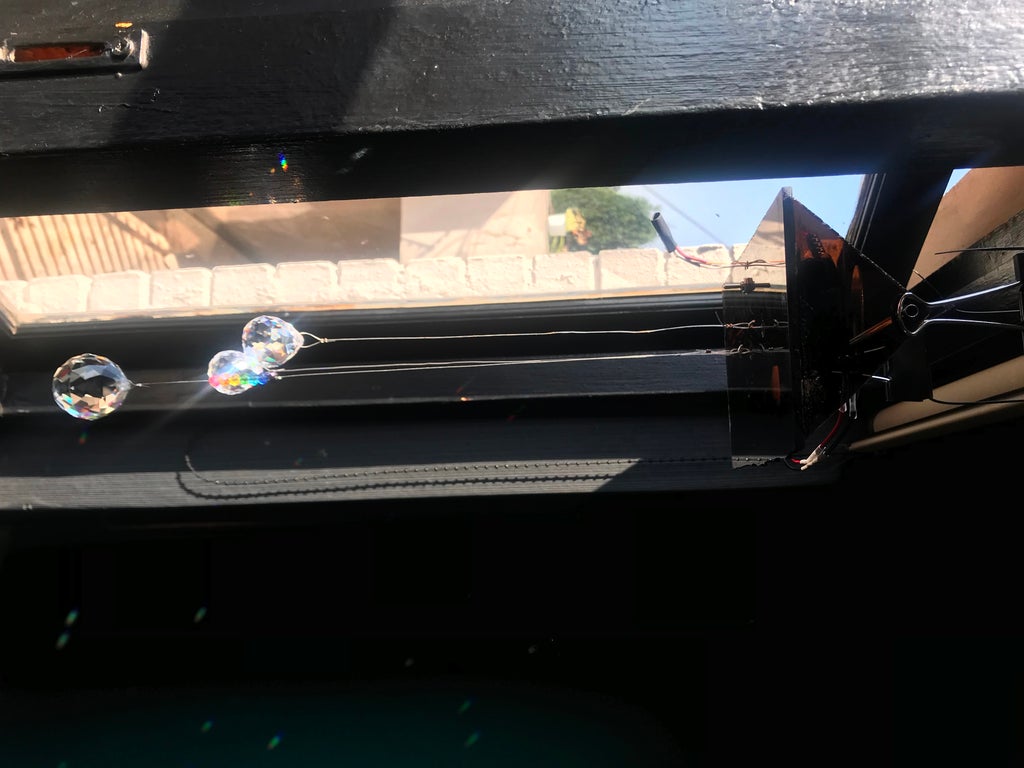
Hang your box in a window that receives plenty light, and hang your crystals from the box. You've done all you can, and physics will handle the rest, refracting the suns light into beautiful rainbows that now move in unexpected but pleasing manners.
To view movement patterns check out the YouTube video @00:48
Step 7: FAQ

Q: It's rather noisy...
A: Noise can be reduced using gear grease and or sealing your up better. Noisy is good though, that's how you know it's working.
Q: Mine doesn't do anything.
A: Is it on? Toggle between the states with the state switch. If nothing is happening, double check you put in your 9V battery.
Q: It's on in one state only.
A: Adjust your trimpot while LDR is in bright light. If still your LDR system isn't working, double check everything is wired correctly.
Q: How do I adjust the Snail Eye LDR again?
A: Screwing the trimpot will adjust at what brightness the MOSFET switches on, trimming the SE-LDR hood will give it a wider field of view and therefore a longer runtime, pointing it at the sun when you would like it to switch on "programs" it for that time of day.
Q: I'm intimidated by my knowledge gaps. Where can I learn more about electronics?
A: Yeah, the knowledge gaps showed themselves to me earlier. A good starting point would be this electronics class by randofo
Q: I have improved on your design/You are mistaken about XYZ.
A: Thank you for helping me close my knowledge gaps, please let me know in comments section.
Q: I have another question.
A: Feel free to ask me stuff in the comments.
Q: Will it work with a disco ball?
A: Yes, Affirmative.

Q: Thank you I love it.
A: Awesome.

Participated in the
Colors of the Rainbow Contest


