

Introduction: Sound Reactive LEDs

Step 1: What You Will Need
In my setup I used two 5m LED strips from Amazon. Each of these strips requires a 2A supply and because I had ordered separately I got two 2A supplies. However you can just use a single 4A supply to power your circuit and your strips. Since I have the circuit with two supplies I will list components according to that.
1> 2 x 5m Led Strips amazon
2> 2 x 2A DC adapters amazon
3> LM324N Quad opamp available at Radioshack
4> 2 x TIP29C transistors
5> 2 x SPDT slide switch https://www.sparkfun.com/products/9609
6> 2 x 100K Ohm resistors, 2 x 5.1k Ohm, 4 X 100 Ohm
7> Wires, Soldering equipment, Solderable PC Breadboard like this
8> 2 x DC Power jack
9> Aux cable(to be stripped at one end)
Step 2: How Others Have Done It Before

Many websites have information about doing it directly with transistors. TIP 29 or 31 can be used. We will discuss circuits, their shortcomings and solutions so a little bit of electronics knowledge is recommended
Audio cable coming out of the PC has three wires in it: Ground, Left and Right. The best way of getting audio signal is to take an aux cable and strip its wires.
If you see bare threads, they are ground and the two insulated ones are left and right
Step 3: How Others Have Done It Before

Connect Ground to the emitter of the transistor and Left or right to the base, connect one end of LED to external power source and the other to the collector of the Transistor
Step 4: Problems With This Circuit

Because currents allowed are really small even with the gain in the transistor it allows only about 40mAs of current to flow at max sound intensity
Voltage of the signal varies from +/-0.8 at max intensity and because of internal voltage drop the transistor gate doesn’t even open till 75% intensity from PC
Even using darlington pairs doesn’t help because of the internal drop. We also want better control for current for running an LED strip instead of a single LED
Step 5: Problems With This Circuit

The transistor allows current to pass through only half the time, The other half of the signal when there is negative voltage coming from the audio is simply neglected so the maximum brightness you get from the LED is only 50%, because the signal is so low you cannot use a diode full wave rectification circuit since the diodes have forward drop of about 0.7V
Step 6: Problems With This Circuit
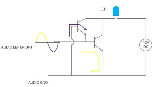
SOLUTION: Connect the audio in the exactly opposite way(ground – base, L/R - emitter) to another transistor and connect the collectors of the transistors together (shown here in figure: colored arrows indicated path of current)
Step 7:
This is where this circuit can get you. (Sorry for the bad taste of music, thats the first thing that came to my mind that day)
Okay so now this circuit can pull 40mA(max) through the LEDs connected in series but the LED strip we have need 2A(max) current for full intensity. There's no other way left to us than to use Opamps. All we are going to do is jack up our signal 20 times( in voltage) and run that through a transistor to control the current.
Step 8: Using Opamps

Step 9: Using Opamps

Step 10: Final Circuit

Step 11: Final Circuit

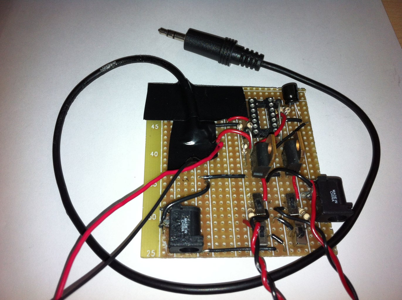
Step 12: Soldered Circuit

Step 13: Setting Up the Lights on the Wall


I used insulation tape to create the surface to paste LED strips on, if you are trying to be low on cost use your creativity!


