Introduction: Standing Linear Actuator; Powered by Modtronix


Some context surrounding the project:
This Linear Actuator was designed for company use; so due to the context of this Instructable, no information will be discussed of the products: they are prototype systems. However I am free to discuss the Linear Actuator itself and how it was built. In addition, I knew that the members of Instructables would appreciate the project.
As I write this, the project is completely finished. I will discuss the Mechanics portion and then the Electrical portion.
How could an Instructables Member benefit from this?
This project demonstrates a practical, sturdy and robust method of lifting and pushing heavy objects; the featured Linear Actuator for example, only stands about 10 inches tall, however it can lift up to 54 pounds! (See the calculations page for the conclusion of this)
This strength is accomplished at a modest price as well; the featured model cost less than $100, not including the electrical. However the electrical is easily emulated through any Micro-controller and simple pieces.
The Instructable even provides suggestions to alternatives for the more intimidating components of the project.
Step 1: Mechanics


There were some mechanical obstacles to overcome when designing the robot. The specs for the project were:
- The robot had to push down and lift up a sealed container to close and open. The weight of the lid on the container does not close the container on its own.
- The project needed to be very robust and strong. It had to run hundreds of times every night.
- The robot shouldn't be ridiculously expensive to create.
- The sealed container did not have to be opened all the way. A couple inch gap would be sufficient.
- The robot needed to hold the bottom of the container down while lifting the lid open. The friction in the seal is enough to lift the entire container.

Learn more about Linear Actuators here: http://en.wikipedia.org/wiki/Linear_actuator
Unfortunately, they are fairly expensive to purchase on their own: roughly $130. Also this Instructable inspired me to build my own:
https://www.instructables.com/id/Making-a-Powerful-Linear-Actuator/
List of Mechanical Parts:
- [1] 90 RPM Precision DC Motor http://www.servocity.com/html/90_rpm_precision_gear_motor.html
- [1] 3/8" Bore 0.77" Clamping Hub http://www.servocity.com/html/0_770__clamping_hubs.html
- [1] 6mm Bore 0.77" Clamping Hub http://www.servocity.com/html/0_770__clamping_hubs.html
- [1] Aluminum Motor Mount http://www.servocity.com/html/aluminum_clamping_motor_mount.html
- [3] 1/2" x 36" Square Steel tubing (Home Depot)
- [1] 3/8" x 12" O.D. Threaded Rod (Home Depot)
- [1] 1/8" x 2" x 36" flat Steel (Home Depot)
- [1] 1/4" x 36" O.D. Steel Rod (Home Depot)
- [2] 3" C-clamps (Home Depot)
See the draft document for the design of the linear actuator. The pieces were professionally machined, welded and painted.
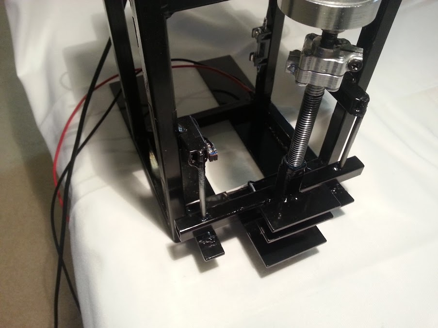
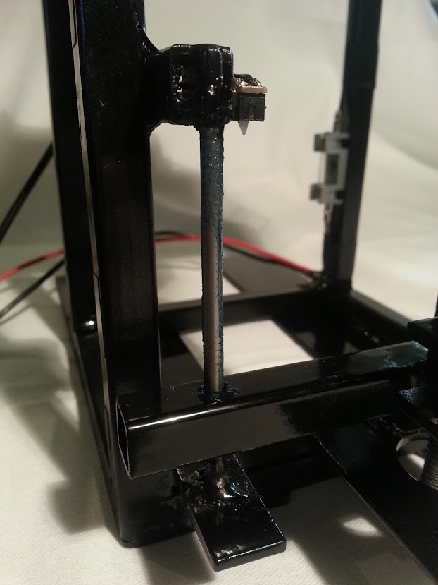
Guiding Rails
The shaft on a Linear Actuator (Shuttle, I'll call it) needed to remain in place and couldn't spin, otherwise the threading would never pass through the nut on the shuttle. So Guiding Rails were implemented in the design. The Guiding Rails hold the shuttle from spinning. They are covered in wheel bearing grease.
DC Motor Diagram provided by Servocity: http://www.servocity.com/html/90_rpm_precision_gear_motor.html
Step 2: Calculate the DC Motor Required

The DC Motors available at Servocity come in several Torque/Speed variations. All the motors are equally priced, however if you would like more speed, you will have to compromise the power. It was necessary for me to determine whether or not the DC Motor I would buy would be powerful enough to open the container.
Also, if you plan on build one of these yourself, you will also need to know whether or not the DC Motor will be strong enough for your application.
The equation to determine the Force to turn a screw is [1]:

A force-gauge was used to measure Q, the force required to open the container. The maximum value obtained was 10.5 Newtons or 2.36 lbs. The friction coefficient of steel on steel is 0.8. The radius of the screw is 0.0047 meters. The pitch thread distance is 0.00106 meters.
Plugging all this in:

This gave me confidence that the 90 RPM DC motor I selected would be strong enough where the load would be trivial.
In the Introduction, I claimed that the featured Linear Actuator was calculated to lift up to 54 pounds. This was calculated trivially. The maximum Torque value of the purchased DC motor is 138.8 oz inches; converting this to Newton meters comes to roughly 0.98 Nm. Keeping the rest of the parameters constant, solve for Q. Q will come to around 240 in Newtons, which is equivalent to roughly 54 pounds.
Keep in mind that this is the weakest/fastest Precision DC motor available on Servocity.com. If you were to purchase the strongest DC motor on Servocity (1,111 oz inches) for the same price, you could lift about 432 pounds!
[1] Machinery's Handbook 21st Edition; Oberg, Jones and Horton; Page 303; Year: 1979
Force Diagram provided by Engineering Toolbox: http://www.engineeringtoolbox.com/screw-jack-d_1308.html
Step 3: Electronics

- (1) Modtronix Engineering IOR5E http://www.modtronix.com/product_info.php?cPath=95&products_id=198
- (1) SBC28PC-IR2 RS232 Daughter Board http://www.modtronix.com/product_info.php?products_id=110
- (1) Serial to Molex Connector http://www.modtronix.com/product_info.php?products_id=103
- (2) Banana Plugs
- (2) Limit Switches
- (1) Fuse Box and 500mA Fuse
12 Volts were used to power the board and DC motor. The ground terminal was directly soldered to the metal frame. Grounding the frame of the project neatens it by eliminating many wires. To ground components, simply solder or bolt them to the frame.
Alternative to Modtronix: Arduino
Any Micro-controller board is capable of controlling the Linear actuator. It must have at least 4 GPIO, which almost any Micro-controller can provide.
An Arduino board for instance, would be perfectly acceptable for controlling the Linear Actuator; you will need to construct an H-Bridge. To build a proper H-Bridge for an Arduino, follow this gentleman's Instructable: https://www.instructables.com/id/Materials-Needed/
The advantage of the Modtronix board is that it's well equipped with relays, making the overall project cleaner since development of a separate board was not necessary. The relays are capable of handling high voltages and currents. A second advantage of the Modtronix is that it came in its own plastic case; further tidying up the project.
Limit Switches and Fuses
Limit Switches were used to detect when the box has fully closed and opened. These were wired from the 5V connector on the Modtronix board to the positive terminal on the Opto Inputs. The negative Opto Inputs were grounded.
An Opto Input is a differential input with a positive terminal and a negative terminal. The negative terminal is the reference voltage to the positive terminal. A voltage difference of positive 3 volts or greater will yield a HIGH on that Opto Input.
To implement a Limit Switch on an Arduino, you would still connect one pin of the limit switch to 5V power, and then have it feed into one the Inputs. Program the Arduino to detect when that pin goes HIGH and deactivate the H-bridge at that moment.

There was still one issue to take into account. The limit switches are relatively weak to the rest of the robot, and would likely be the first to fail. If this was to happen, then the DC motor would never stop turning because the switch wouldn't trip the Opto Input. This could potentially cause the Motor to fail. Therefore, a fuse is required.
Using a Multimeter, an amperage of 300mA was consumed while the DC motor is under normal operating conditions. On Servocity's website, the stall current is at 1 Amp. The fuse value I chose was 500mA. This was wired in series to the Voltage source.
Step 4: Tips on Using the Modtronix Set


If you would like the challenge of the Modtronix Components:
The IOR5E is an Input/Output board with 5 relays. This board also has 5 Opto Inputs and 5 normal inputs. Opto inputs are essentially differential inputs; each Opto input needs two connections. One for reference and another for control. The Opto input reads HIGH when the control is 3V or higher than the reference.
The Daughter Board for the IOR5E interfaces to the power source and enables the RS232 functionality.
Wiring an H-bridge is easy with the IOR5E. Taking a 12 volt source, Vcc goes to 1C and 2C, and ground goes to 3C and 4C. When the relays close, the Normally Open (NO) connectors get the value the respective C has. For instance: when Relay 1 flips on, NO gets 12 volts.
Now connect NO of 1 and NO of 3 to one terminal of the DC motor, NO of 2 and NO of 4 connect to the other terminal.
You don't have to worry about back EMF, the relays are already protected.
Programming
For the Programming portion, a library created in Python by one of my co-workers was used. I coded my own Python and used it as a wrapper around the library. The code is not written directly to the Modtronix board, but rather a script using SLIP is used to communicate. It works by turning on the appropriate relays and waiting for the limit switches on the robot to trip, detecting when fully closed or open. It then switches those relays off.
The original library however is not mine to disclose so unfortunately I cannot share this to the internet, rendering my code useless to you since mine is built from it.
I will however give you pointers on how to interface to the Modtronix so you can be well on your way to creating your own library. If you are competent in C, it will likely be of little challenge.
The Modtronix uses SLIP to communicate from the computer to the board. SLIP is defined in RFC 1055 (http://tools.ietf.org/html/rfc1055) and goes into the details of how it works exactly. On top of this, an example send and receive C program is contained within the RFC.