

Introduction: Strandbeest Photovore Robot


I have been fascinated with Theo Jansen's walking beach creatures for some time. So I read with interest the April 2014 Servo Magazine article about converting the plastic model kit to be servo-powered. The idea of the Strandbeest walking around my studio fascinated me.
Ebay seems to be a good place to purchase the kit from. As you can see, there are a lot of little parts in the kit. The Servo Magazine article has a good description of how to assemble the kit, so I won't go into that here. My addition to the project is to use 3D printed parts for the servo support, and to add photoresistors and bump sensors to make the robot a bit smarter.
Step 1: Parts


You will need:
photocells - 2 matching ones available from electronics suppliers
Arduino Pro Mini - $10 from Sparkfun
2x 9 gram servos - I used MG90S Tower Pro servos from Ebay
9 volt battery
9 volt battery leads
micro switch for on/off
L298N motor driver - also from Ebay for about $3
2 x 10k resistors
some springy wire for feelers - I use metal guitar string or thin piano wire
Strandbeest kit
epoxy putty
solder and soldering iron
small screwdrivers for opening the servo
3D printer for parts
spray primer
paints
Step 2: Hack the Servos


There are many posts out there about turning regular servos into continuous rotation servos. The first step is to take the servo apart by unscrewing the four screws that hold the body base to the top. You will need to cut off the stop on the output gear. There's a tab that keeps the gear from rotating fully. You want to remove that.
You can remove the potentiometer and replace it with resistors. Again, there are many posts out there that describe how to do this.
I just removed the potentiometer and the control circuit completely. Then I soldered wires onto the motor directly. These wires run up to the L298N module. The Arduino sends commands to the L298N and it sends power to the motors. It is also possible that you could use relays to turn on the servos if the power is directly connected to the motor and not through the control circuit.
And, you can mod a servo to be continuous rotation. See the Adafruit tutorial.
If you use the L298N module, here is a good tutorial-
Step 3: Connect the Drive Shaft


I have attached the 3D Base print that I created. The metal bars that hold the legs assemblies together go through the holes. I had already attached the servo to the crankshaft. I used epoxy putty. I think you could do a neater and more efficient job if you used a servo coupler. I have added a couple of links to possible parts that can be 3D printed.
Basically, I ran the rods with leg assemblies through and then saw where the servo needed to sit. I used a Dremel with a small drill bit and made holes through which I ran zip ties to hold the servos in place.
There was a perfect amount of room between the servos to put a 9 volt battery, so I used double-backed sticky tape to hold it in place.
Attachments

Step 4: The Upper Deck and Wiring


In my first iteration, I used foam core, wire and a couple of plastic balls to make the "eyes" to hold the photocells. But it was pretty ghetto.
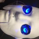
Using Sketchup, I created a steampunk eye, eye stem, eye mount, and upper deck. I wasn't sure how it would all fit together, so I didn't create sockets. You will have to drill holes in the eye mount to get the eye stems in place, and then super glue them in. I used a tiny screw and drilled a pilot hole to hold the eye back to the eye stem. Eye fronts are from the Hollow Sphere 3D file on Thingiverse.
I used the scale function to enlarge the eye mount because I thought it looked too wimpy and out of proportion. I had already connected the photocells up, so I drilled out a hole in the back of they eyes to run them through.
The upper deck has a spot for the Arduino and for the L298N module to sit.
The "whiskers" are just springy wire attached to one wire, and then a bolt attached to the second whisker wire. When the whisker is bent back, it touches the bolt and acts like a button.
I used pins A0 and A1 for the whiskers. Basically, they are just buttons and you can find a tutorial on how to connect them HERE . I used digital pins 2,3,4 and 5 to control the L298N module. You can find a tutorial on how to connect it HERE .


Step 5: Make It Cool


I attached the upper deck and eye fronts to a wooden 2x2 and gave them three thin coats of primer.
Next I sprayed the eye fronts with spray chrome, and the upper deck with oil rubbed brass spray paint. After the paint was completely dry, I dry brushed on some metallic acrylic paints to bring out the highlights. Lastly, I finished it off with a matte coat of clear sealer spray.
All that remained was to cut out holes in the rear of the eyes to run the wiring to the photocells through, and then assemble all of the parts.
I have included the code I used to control the robot.
The video shows how a flashlight can control the robot's movements. In the end he heads merrily across the garage floor.


