

Introduction: Super Fast Paper Plane Launcher


In the last step I added a template to help children fold a plane that works great with the launcher. The template also shows how decorations are affected by the folding (two pilots becoming one).
See how it works in the following videos (I did not select the fastest launches as this way you get to see something):
The device can launch a large range of models. As long as there is vertical and longitudinal bottom section at least about 1 cm height, it should work. You can find the principle in a number of other applications. As a kid I had toy accelerating matchbox cars on a track in a similar way. The Science Museum in London carries kits to make either a paper plane launcher or a Ping-Pong ball canon. In this instructable I explain how to build a battery powered paper plane launcher for less than 5 euro. If someone with a little experience (or willing to learn) does the soldering and hot melt gluing in advance, the construction and use makes a great childrens activity. It involves cutting and folding paper, nailing, some ordinary gluing and decorating. The high speed is not the best way to reach distance records, although it does allow children with less tossing skills to reach new personal records. Most importantly it is quite spectacular and great fun. Putting fingers between the fast turning wheels will be painful. But if you keep to the power of two AA batteries, there is no real danger of injury. Do avoid launching towards people, animals ore anything fragile. Of course, I can not accept any liability.
I first published this instructable arround the time of the "Toss it! Speed contest". Of course it did not compete in that contest as it involves battery powered launching instead of tossing. It still was a good time because of all those inspiring entries in the "Toss it! Speed contest", which made this launching device did come in handy.
Step 1: Parts, Materials and Tools
For the main parts I included some tips wher you can buy them online, [www.opitec.com Opitec] for Europe and Kelvin [www.kelvin.com Kelvin] for US & Canada. Of course you can also use parts you find elsewhere.
Here is the list:
- 2 small electric motors of nominal voltage 3 V (ref. 224.013 at Opitec or ref. 850646 at Kelvin)
- 2 wooden wheels about 4 cm diameter, with rubber tyre (ref. 601032 at Opitec. At Kelvin you can only find wooden wheels without tyre, ref. 390394, I explain some alternatives to add tyres in step 7.
- adapters to fit the wooden wheels to the motor shafts (ref. 842022 at Opitec or ref. 390632 + 990317 at Kelvin, I explain an alternative in step 8.
- a (pushbutton) switch (ref. 213011 for a pack of 10 at Opitec)
- two batteries (AA), a battery holder (ref. 206019 at Opitec) and a connector for the battery holder (ref. 207058 at Opitec)
- about 30 cm of electric wire
- plywood board about 3 to 5mm thick x 100 mm x 300 mm
- 3 pieces of timber about 15mm x 40mm x 200mm
- 9 or more small nails about 15mm long (at least shorter than the thickness of your board and your timber together)
- a (small) hammer
- scissors
- 2 (quick release) clamps
- a pencil or a fine marker
- some cellotape
- glue (superglue, white glue or childrens' crafts glue)
- a hot melt glue gun and some glue
- soldering iron and a little solder
- Acrobat Reader, a printer and A4 paper to print the templates
- optionally a washer fitting on the switch and a drill making holes allowing the switch go through completely and also the battery connector (with classic push button switches and connectors often a diameter of 11 or 12 mm should do it).
Step 2: Preparations Requiring Just a Little Experience


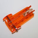
Cover one of the pieces of timber (or a similar one as you will need all three later on) with anti-stick baking paper. Tape it tightly around the wood. Mount the wheels on the motors and position them on the prepared piece of timber with the tyres just touching each other or at the most 1 mm apart. Clamp the wheels in this position as shown in the first picture. Put some hot melt glue on the motors to form an assembly as shown in the second picture. Do avoid pouring any glue in any holes of the motors. After the glue has set, remove the assembly. If you are planning to have children assemble the device, remove the wheels in order to allow them mounting them their selves.
Solder the wiring as shown in the fourth picture. Note the motors are wired in parallel, but with opposite polarity (they need to rotate in opposite direction). The rotating direction of the combination can be corrected with the polarity of the batteries, so you do not need to worry about that, at this stage.
Later on, you can attach the switch anyway you want, but included in this instructable is an option that makes mounting it real easy for kids building the device. It involves drilling a 12 mm hole in one of the pieces of timber, at about 11 cm from one end. See the last picture. You can do that in preparation, but if you have a pillar drill setup available, even young kids can do that themselves under close supervision.
Step 3: The Easy Work Starts: Nail It!


Print out the template included below (it is best to print it at 100% by disabling the scale to fit page option when printing from Acrobat Reader). Cut it as shown in the pictures and use it to mark the two rectangles and the point of the arrow on BOTH FACES of your plywood board.
You now start out with one of the pieces of timber. If you go for the option to attach the switch with a washer, you should take the one with the hole. Put this piece under the edge of the board with the mark of the arrow as shown. The optional hole should not be under the board. Fix it with at least three nails, avoiding putting a nail close to the mark of the arrow (in order to avoid your plane remain stuck on it, later on).
Attach the other two of the pieces of timber in place (on the marked rectangles) provisionally with a piece of double sided tape each. Turn the board around and attach the pieces permanently with at least three nails each.
Attachments

Step 4: Just a Little Trickier Again: Glue It!


Using the adapters mount he wheels on the motors. Some careful tapping with a hammer might be needed. Make sure the other end of the motor shaft is resting on a surface that can resist the hammering. Leave a little space between the wheels and the motor bearings. This is important to have the wheels turn smoothly. Position the assembly on the wooden construction as shown. Make sure the point where the wheels touch is aligned with mark of the arrow and that the wheels can move freely above the plywood board. Glue it in this position with the glue of your choice avoiding any holes and bearings of the motors. I do recommend using superglue. You can simply apply some drops at the edges of the hot melt glue, where it touches the wood and let the superglue soak in. In a workshop, after warning the kids not to glue their fingers, I have them holding the assembly in position and I go around with my superglue. With the younger kids I apply the drops of superglue myself.
Step 5: Fitting of the Pushbutton Switch: a Suggested Option


You can attach the switch in several ways, but this is the way involving the optional washer and hole: First put the battery connector through the hole and then the switch. Screw the washer on the switch and fit it back in the hole. Attach the battery holder and fit the batteries. Push the button to check if it is working. Check the direction of rotation of the wheels. Of course, at the point where the two wheels meet, they should move away from the rest of the construction. If this is not the case, reverse both batteries. Stick the battery holder under the plywood board with some double-sided tape or glue.
The launcher is ready; all you need now is a paper plane. (next step)
Step 6: Finally Making a Plane (with Template) and Launching It!


Print out the template included below (it is best to print it at 100% by disabling the option "scale to fit page" when printing from Acrobat Reader). Fold it following the indications on the template itself and the pictures below. For use with the launcher it is useful to put some cellotape to hold the fold closed at the nose end. It also is a good idea to cut a piece of the nose as shown. The high launching speed often results in a buckled nose section, which makes it harder to launch another time. A nose cut a little shorter is les prone to that.
In the beginning, putting the device on a table is very practical. Put the plane in the guiding made by the two parallel piece of timber. To launch, push the switch to let the wheels spin up to the desired speed. While keeping the motors switched on, gently push the plane forward until its nose is caught by the spinning wheels and the plane is hurdled forward. Check the movie in the introduction.
Attachments
Step 7: Adding a Rubber Tyre to a Small (wooden) Wheel

You can make a groove in the wheel and mount a round rubber joint with a diameter slightly smaller than the wheel. This works best with wooden wheels. You can find rubber joints in many sizes in the better stocked Do-it-yourself store. The groove can be made with a power drill as an improvised lathe, as long as you can firmly mount the power dril and have a stable support for the "chisel". You do not need a real chisel. I use a large file. be carefull though! .
The second alternative is cutting some rings from using bicycle inner tubing and mounting them on the wheel. You can use a number of layers to achieve the desired diameter. The picture shows the result.
Step 8: Adapting Wheels to Smaller Diameter Axles or Shafts


The sollution is making use of the brass tubing available in moost moddeling shops in "telescopic" sizes. This means the outside diameter fits inside the next tube. You start with a tube fitting the axle or shaft and add tubes untill it fits the hole in the wheel or gear. If you do not arrive at a good fit, drill out the hole to a fitting size.
Cut the brass tubes to a length about equal to the thicknes of your wheels or gears. The tubes can be cut quite cleanly with a snap off knife, with a rolling movement as shown in the video. Do not use a knife you want to cherish, as this will cost you in lifetime of the knife's cuttin edge. You might still have to remove some burs. At the inside you can do that carfully with the tip of the same knife. At the outside you can use a file or sanding paper.
Fit the wheel and tubes "telescopically" and add a drop of superglue. Avoid getting glue in the inside of the smallest tube, unless you want to apply the following trick: if the fit with the axle or shaft is lose while it should be thight do not attempt glueing it on a motor shaft or any other axle already mounted in any bearing. You risk gluing it stuck in the bearing or at least to add a lot of friction. Instead, put some superglue in the inside of the smallest tube and immediatly and forcefully blow it out again with a straw (the latter is to avoid getting glue on your lips). Let it dry out before mounting. The thin layer of glue will provide a tight fit.


