

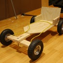
Introduction: Sweeping Ultrasonic Rangefinder


• Arduino Uno or compatible board (e.g. Freetronics Eleven)
• Protoshield and stackable female headers
• Adafruit 1.8” TFT Display with male header pins
• Servo
• MaxSonar Ultrasonic rangefinder
• 5V BEC Step-down Voltage Regulator (or solder your own 5V regulator circuit onto the shield)
• Right-angle male header pins
• Breadboard jumpers
• Female-female jumper wires
• 9V battery holder with 2.1mm plug
Attachments

Step 1: Soldering


- Solder header pins onto the Adafruit TFT Display shield. More details may be found here: http://learn.adafruit.com/1-8-tft-display
- Solder stackable headers onto the protoshield. Follow the link for more details: http://www.freetronics.com/pages/soldering-shield-headers#.UxGqFu_NvX4
- Perform the next step however you like. The intention is to be able to connect the GND and 5V wires from the BEC to the servo wires, along with the digital pin used for the servo control signal. You could get away without the protoshield altogether, however it allows you to hide away the jumper wires.
- Solder a 3-pin right-angle header onto the shield. The BEC will connect to this.
- Adjacent to this, solder another 3-pin right-angle header facing the opposite direction. This is where the servo will be connected.
- Make solder jumpers between adjacent pins on the right-angle headers.
- Use a breadboard jumper to connect Digital Pin 9 to the nearest header pin on the servo headers. This will connect to the servo singal wire (either white or orange). We will use Digital Pin 9 for the servo signal.
- Solder some 1-pin right-angle headers to Analog Pin 0 and the GND and 5V lines. These will be used for the Ultrasonic sensor.
- Solder header pins to the Ultrasonic sensor.
Step 2: Assembly Part 1


- Connect the battery holder to the Uno with a 10mm M3 bolt and nut. Also connect the positive and negative jumpers from the BEC and the battery holder to the same 2.1mm plug.
- Connect the ultrasonic rangefinder to a servo arm using a right angled bracket. This can be fashioned from scrap plastic - or just use a decent blob of Blutak.
- Secure the bracket to the servo.
- Secure the servo to the TFT display with a 10mm M3 bolt and nut.
Step 3: Assembly Part 2


- Stack the shield you made earlier on top of the Uno.
- Connect the BEC outputs to the right-angle header. Connect the servo wires to the right-angle header opposite. Make sure positive is connected to positive and negative is connected to negative.
- Connect the Analogue Pin 0 header to the Analogue output (Pin 3) of the Ultrasonic sensor via an F-F jumper wire. Do the same for the GND and 5V pins.
- Arrange the wires and BEC as neatly as possible on the shield and then stack the TFT Display on top.
Step 4: Upload Code

- Connect the Uno to a PC via USB. Copy the code shown below into a blank sketch using the Arduino IDE and upload it to the board.
- You will need to import the ST7735 and Adafruit GFX Libraries which are found here: http://learn.adafruit.com/1-8-tft-display/graphics-library
- Remove the USB cable and attach the 2.1mm plug to the Uno’s power jack.
- You now have a working Sweeping Ultrasonic Rangefinder. Play around with some of the variables to in the code to change the speed of the servo and way the results are plotted on the display.
// This code processes data from an ultrasonic rangefinder mounted on a servo
// The servo will sweep 180 degrees
// Data from the ultrasonic rangefinder is plotted on the display
// For the breakout, you can use any (4 or) 5 pins
//#define sclk 4
//#define mosi 5
//#define cs 6
//#define dc 7
//#define rst 8 // you can also connect this to the Arduino reset
//Use these pins for the shield!
#define sclk 13
#define mosi 11
#define cs 10
#define dc 8
#define rst 0 // you can also connect this to the Arduino reset
#include <Adafruit_GFX.h> // Core graphics library
#include <Adafruit_ST7735.h> // Hardware-specific library
#include <math.h>
#include <SPI.h>
#include <Servo.h>
#if defined(__SAM3X8E__)
#undef __FlashStringHelper::F(string_literal)
#define F(string_literal) string_literal
#endif
Adafruit_ST7735 tft = Adafruit_ST7735(cs, dc, rst);
float p = 3.1415926;
uint16_t x = 0;
uint16_t y = 0;
float angle = 0;
float angle2 = 0;
float angle1 = 0;
int forward = 1;
int sensor = 0;
double distance = 0;
uint16_t px = 0;
uint16_t py = 0;
double scale = .4;
int i = 0;
double speed = 0.02;
float offset = 10;
int count = 0;
int pos = 0;
Servo servo;
int servopin = 9;
void setup(void) {
// Attach servo and set to centre position
servo.attach(servopin);
delay(500);
servo.write(90);
delay(500);
servo.detach(); // Detach before sending display commands (SPI interface uses same timers are Servo library)
tft.initR(INITR_BLACKTAB); // initialize a ST7735S chip, black tab
// If your TFT's plastic wrap has a Red Tab, use the following:
//tft.initR(INITR_REDTAB); // initialize a ST7735R chip, red tab
// If your TFT's plastic wrap has a Green Tab, use the following:
//tft.initR(INITR_GREENTAB); // initialize a ST7735R chip, green tab
// Make a black screen and then print background (text and arcs)
tft.fillScreen(ST7735_BLACK);
tft.setCursor(0, 152);
tft.print(" 1m 2m 3m");
tft.setCursor(0, 0);
tft.print("SCANNING");
drawcircles();
angle1 = atan((float)tft.width()/((tft.height()/2.0)-offset));
angle2 = M_PI - angle1;
}
void loop() {
// Calculate position for servo (servo is 0-180degrees whilst angle variable is in radians)
pos = 180.0-180.0*(angle/p);
distance = analogRead(sensor);
// Atach servo at the start of each loop
servo.attach(servopin);
delay(15);
servo.write(pos);
// This code converts polar cooridantes of sensor to x-y coordinates
// This determines which pixels to draw the sensor data on
// The code varies slightly depending on the quadrant of the angle
if(angle<angle1) {
x = (uint16_t) (tft.height()/2-offset) * tan(angle);
y = (uint16_t) offset;
px = scale * distance * sin(angle);
py = tft.height()/2 - scale * distance * cos(angle);
} else if(angle<(M_PI/2.0)) {
y = (uint16_t) ((tft.height())/2 - tft.width() / tan(angle));
x = tft.width();
px = scale * distance * sin(angle);
py = tft.height()/2 - scale * distance * cos(angle);
} else if(angle<angle2) {
y = (uint16_t) ((tft.height())/2 + tft.width() / tan(M_PI-angle));
x = tft.width();
px = scale * distance * sin(M_PI-angle);
py = tft.height()/2 + scale * distance * cos(M_PI-angle);
} else if(angle>angle2){
x = (uint16_t) (tft.height()/2-offset) * tan(M_PI-angle);
y = (uint16_t) (tft.height()-offset);
px = scale * distance * sin(M_PI-angle);
py = tft.height()/2 + scale * distance * cos(M_PI-angle);
}
// Detach the servo after it has reached it's position for the cycle and before writing display commands
delay(15);
servo.detach();
// Draw a line representing the direction the sensor is pointing
tft.drawLine(0, tft.height()/2,x,y, ST7735_GREEN);
tft.drawLine(0, tft.height()/2,x,y, ST7735_BLACK);
// Draw a circle for the sensor
tft.fillCircle(px, py, 1, ST7735_RED);
// As drawing objects is computationally intensive, the green arcs are only drawn every 30 cycles
if(count>=30) {
count = 0;
drawcircles();
tft.print(" .");
}
count++;
// This code changes the direction the servo rotates when it reaches the end of each sweep (0 or 180 degrees)
// The code includes re-drawing the text and arcs as the display is cleared at the end of each sweep
if(forward==0) {
angle=angle-speed;
if(angle<=0) {
angle = 0;
forward = 1;
tft.fillScreen(ST7735_BLACK);
tft.setCursor(0, 152);
tft.print(" 1m 2m 3m");
tft.setCursor(0, 0);
tft.print("SCANNING");
count = 0;
drawcircles();
}
} else {
angle=angle+speed;
if(angle>=M_PI) {
angle = M_PI;
forward = 0;
tft.fillScreen(ST7735_BLACK);
tft.setCursor(0, 152);
tft.print(" 1m 2m 3m");
tft.setCursor(0, 0);
tft.print("SCANNING");
count = 0;
drawcircles();
}
}
}
// A function for drawing circles
void drawcircles() {
tft.drawCircle(0, tft.height()/2, tft.height()/4-20, ST7735_GREEN);
tft.drawCircle(0, tft.height()/2, tft.height()/2-20, ST7735_GREEN);
tft.drawCircle(0, tft.height()/2, tft.width()-20, ST7735_GREEN);
}

Participated in the
Arduino Contest


