

Introduction: Teensy MIDI USB Foot Controller for Controlling Mobius Looper


Motivation:
Playing in a 2 piece band, with the drums and lots of other samples being played back as backing tracks, there was a need to use a looper to add in more elements to the tracks. A hardware based looper fails in this respect, since there is no way to maintain synchronisation. Meaning, slight discrepancies between triggering the start loop and end loop, even if it's ever so minute, will add up as the bars progress, and since there's no drummer to adapt to the loop, it will eventually run off time.
Thus, a software based looper is the way to go. Not just because you can maintain tempo based synchronisation on the DAW software that you're hosting the plugin, but also because most of these software loopers are free, and more functional than a hardware looper could ever be.
There are quite a few to choose from:
Since your arms are occupied with the daunting task of playing an instrument, you need to control the parameters of the looper through your foot. This is where the midi foot controller comes in. If you aren't familiar with what MIDI is, here an article.
Many midi controllers are available in the market, and the Beheringer FCB1010 is one of the most popular ones out there. But the perks of building you're own are:
- Cost: you can build one for 1/8th the cost of a commercially available one.
- Customization: You can build a controller as per your requirement. This controller has the specs that I want, your needs maybe different. This instructable is thorough enough to act as a guide for a generic midi controller, rather than being confined and limited to someone else's project.
- It's USB bus powered, there is no need for an external power supply.
- And the perk which is often ignored the most, it's fun ! You get to learn something new, and you'll have something to show for your efforts by the end of it.
The concept is quite simple and straightforward. You press a button, the arduino interprets the signal arriving from the button as a midi "control change" signal (typically represented as MIDI CC), and this signal can be mapped to respond to any of the parameters of the looper.
Step 1: Getting Started..
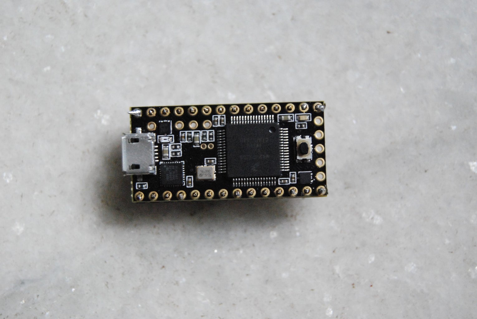
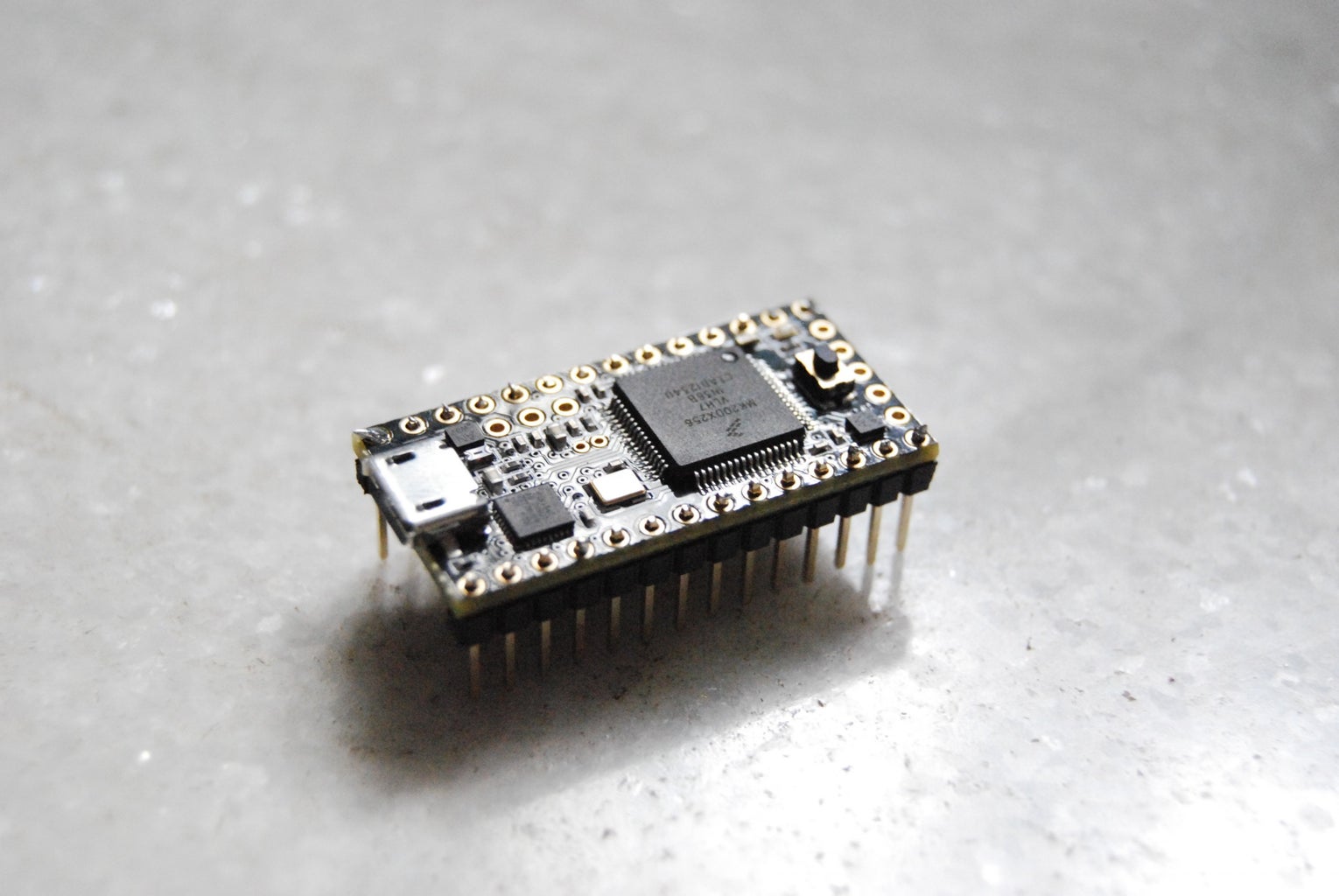
This project can be done using any micro-controller based on the arduino architecture. I chose a Teensy 3.1. The reason for this has been elaborated in this article.
Hardware list:
- Arduino
- Momentary switches
- 10k resistors
- 1k potentiometer
- Tapered LED
- Resistors for LED
- 2X16 LCD Display
- USB Cable Micro-B
- Breadboard (for prototyping)
- Perforated board
- Jumpers and wires
Software list:
- DAW software of choice ( I use Reaper )
- Mobius
- Arduino IDE
- Teensyduino (If you are using a Teensy as your micro-controller)
- MIDI OX
Tools and misc:
- Power drill
- Jigsaw
- Soldering iron, solder, flux
- Scraps of plywood
- Plate of Aluminium
Skills required:
WARNING: This tutorial involves the operation and usage of power tools, which when handled improperly, may lead to injury, and in ridiculously dumb circumstances, fatality. If you've never used power tools before, go to your neighborhood workshop and ask for assistance. If you are under 18, supervision is strictly required. I shall not be held accountable for any losses that a user of this instructable may sustain, either financial, physical or mental(??).
Basic electrical skills such as soldering, is required.
Coding skills are optional, you are provided the code. But it's advisable to have a background in C/C++ to be able to modify and change parts of the code according to your requirements. For anyone with a background in coding, Arduino programming is very simple and straightforward. Here's some material that can help you get started with arduino programming.
I'll split this tutorial into four parts:
1) Prototyping with a couple of inputs
2) Hardware build
3) Assembly, and basically putting it all together
4) Operation
Step 2: Prototyping
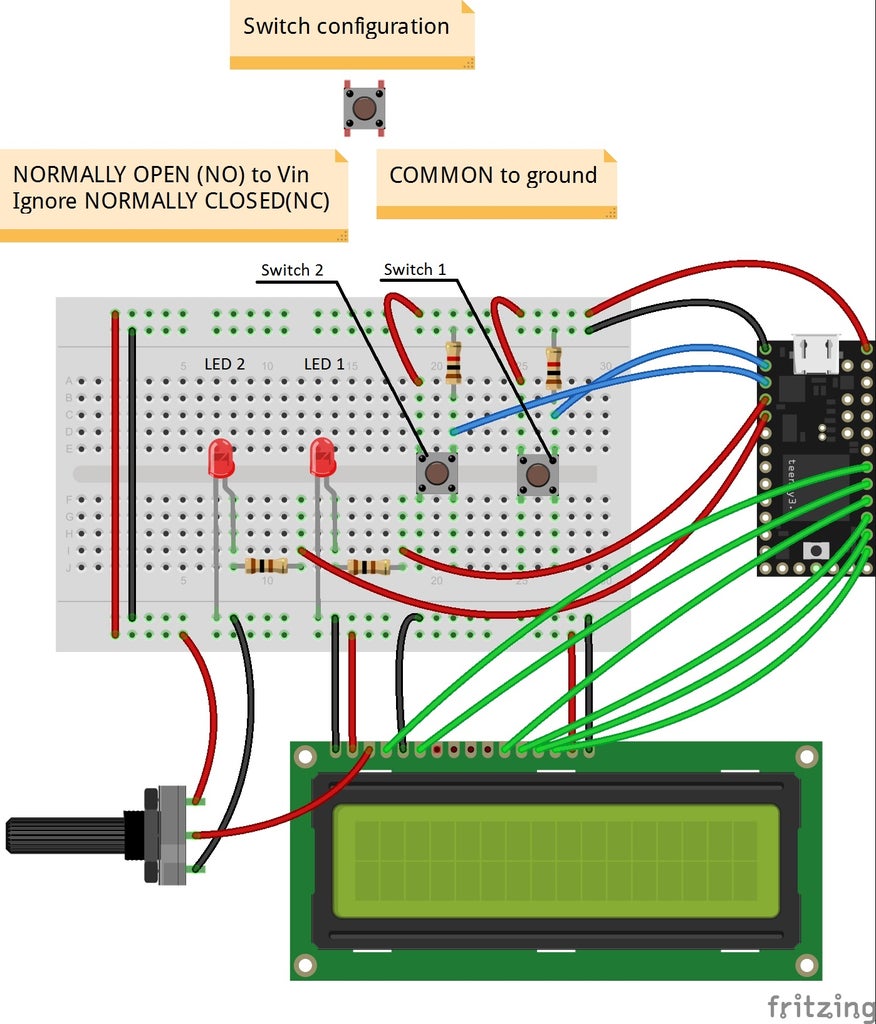


Before you start off with the main build, it's much more convenient to test out the design and see if everything is working. So for this stage, we will set up 2 switches with the Arduino, on pins 0,1 as INPUT, and 2 corresponding LEDs for notification on pins 2,3 as OUTPUT. A 16X2 LCD Display can also be included in the circuit. Generally, an LCD display of this sort has 16 pins. Heed to the order of the pins, numbers 1 and 16 are usually printed as a guidance. The pinout for the LCD display as as follows:
- Ground
- Supply voltage for logic ( +5v supply )
- Operating voltage for LCD contrast ( middle pin of potentiometer )
- Instruction code ( pin 19 on teensy )
- Read/write signal ( not connected )
- Enable signal ( pin 18 on teensy )
- Data bus 7 ( not connected )
- DB 6 ( not connected )
- DB 5 ( not connected )
- DB 4 ( not connected )
- DB 3 ( pin 17 on teensy )
- DB 2 ( pin 16 on teensy )
- DB 1 ( pin 15 on teensy )
- DB 0 ( pin 14 on teensy )
- Ground
- Power supply for LCD ( +5V supply )
A Fritzing diagram is as shown.
- A 10k resistor is used with the switch as a Pull-down resistor. Meaning, whenever the switch is not toggled on, it is pulled to the ground, so that it is not affected by erroneous noise signal which may be present due to other active devices. Simply speaking, when the switch is off, the resistor ensures that it is off. Any value from 1k - 100k will do.
- Choosing the resistor value for your LED. The following tutorial explains how you can choose the resistor value for the LEDs you have.
There is another way to determine the required resistance. Use a 10k potentiometer, connect one wire from from the longer edge of the LED to the wiper, or middle pin of the pot. Connect a wire from either of the pins of the pot to one of the digital pins on the arduino. Now rotate the wiper till the LED glows sufficiently bright, then measure the resistance across the pins using a multimeter. This is a raw estimate of the required resistance.
Always use an LED with a resistor. An LED glows the brightest without one, but since there is nothing limiting the current from the arduino to the LED, the entire available current is transferred to the LED, which will ruin it in the long run.
Once the circuit is done, connect your arduino to your PC using a USB cable. Follow the instruction below, if you've never used an arduino before. This basically explains how to compile and upload an already existing code(or sketch, as they call it) onto your arduino.
Also, remember to set the device as a midi device.
Select "MIDI" from Tools -> USB type.
The code for this prototype is uploaded below. It is thoroughly commented and is self explanatory.
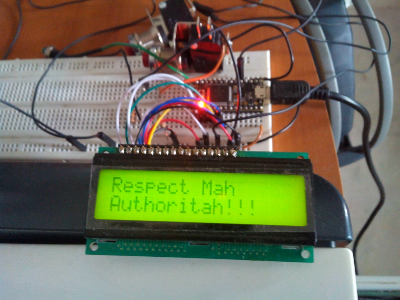
Now, we test if the circuit and code are functional.
Press both the buttons, do the corresponding LEDs light up ?
To test if the computer is actually receiving any MIDI signal from the button you just depressed, you need the software, MIDI OX, installed.
In MIDI OX, go to Options -> MIDI Device, and select your device. Mine shows us as Teensy MIDI.
Whenever, you press and release a button, an output similar to this should show up. Are you getting a similar output ?
If everything goes fine, we conclude that all the components and code are working fine, and we can move on to building an enclosure for the project.
Attachments

Step 3: 2) Hardware Build


Woodwork
For my Midi footswitch project, I used scraps of available plywood, around 10mm in thickness, for the base and the sides of the enclosure. Cut out pieces to make an enclosure of dimensions 70 X 13 X (10,6) cm. To align everything in place, we need to cut out box joints or finger joints on the edges of the work pieces which fit together. The following material explains what box joints are and how you make them.
Cutting out box joints precisely, by hand, is painstaking work. If you have router table, a very simple box joint jig can be fashioned and the job can be done in a jiffy. Since I do not have a router table or any workbench for that matter, I had to resort to doing it by hand.
Regular Butt joints, and just nailing the wood pieces together will NOT give it enough structural strength required to sustain hours of being stomped on!
After it's finished, it should look something like this.
I nailed the bottom base piece to the rest of the contraption, and filed off protruding edges of the box joints, and I glued the joints together using wood glue. I had some laminate material left over, so I cut out piece of it, and stuck it on to the outer surface to make it look nice !
Metal work
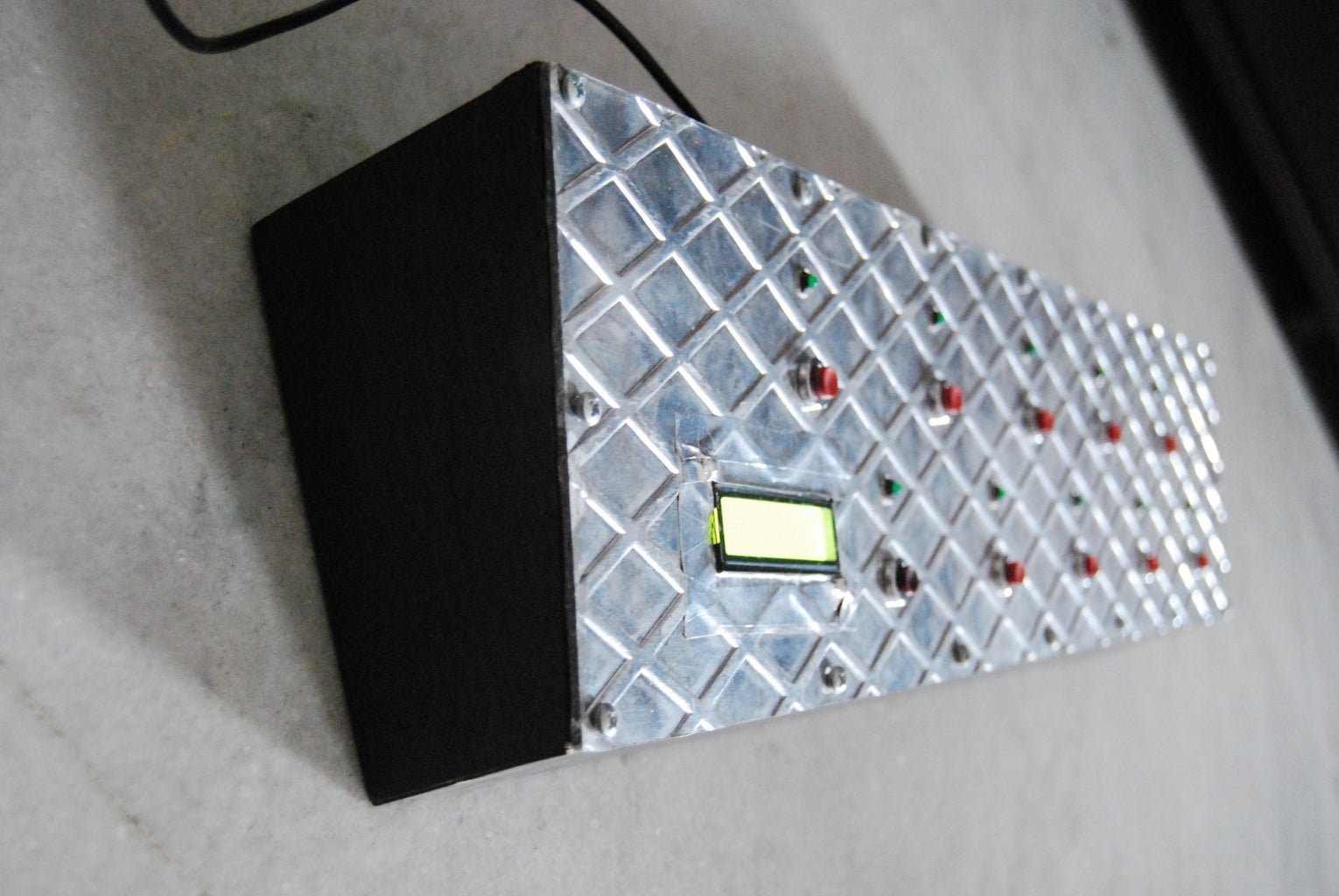
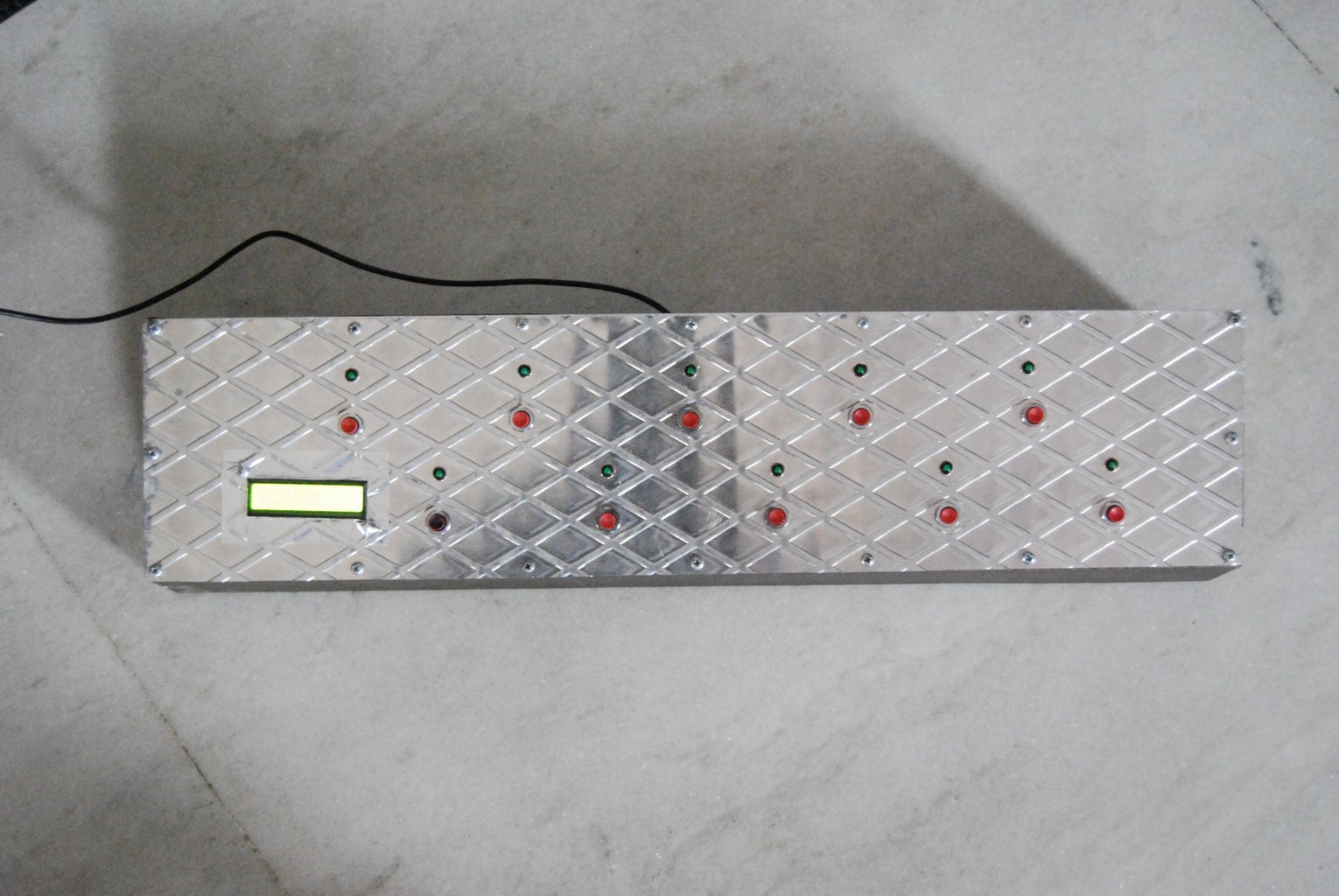
For the piece that goes on the top, I could only use a maximum of 5mm thick wood, since the groove on the LED to be screwed in, allowed only that much. I decided to use an aluminium plate instead. The plate that I used is about 3mm in thickness, and has a sort of honeycomb pattern on it (which I thought was pretty cool).
I cut out the exact dimensions to fit the box that we've made, using a jigsaw and metal cutting blade. To cut out the holes to encompass the switches, the LEDs, the LCD display and to fasten screws, I used 2 drill bit sizes. A 12/32 inch bit for the switches, and a 8/32 inch bit for the LEDs and screws. For housing the LCD display, I marked out the rectangular dimensions on the plate, drilled two holes on opposite sides and used a jigsaw to cut a rectangular slot in the plate.
Step 4: 3) Assembly

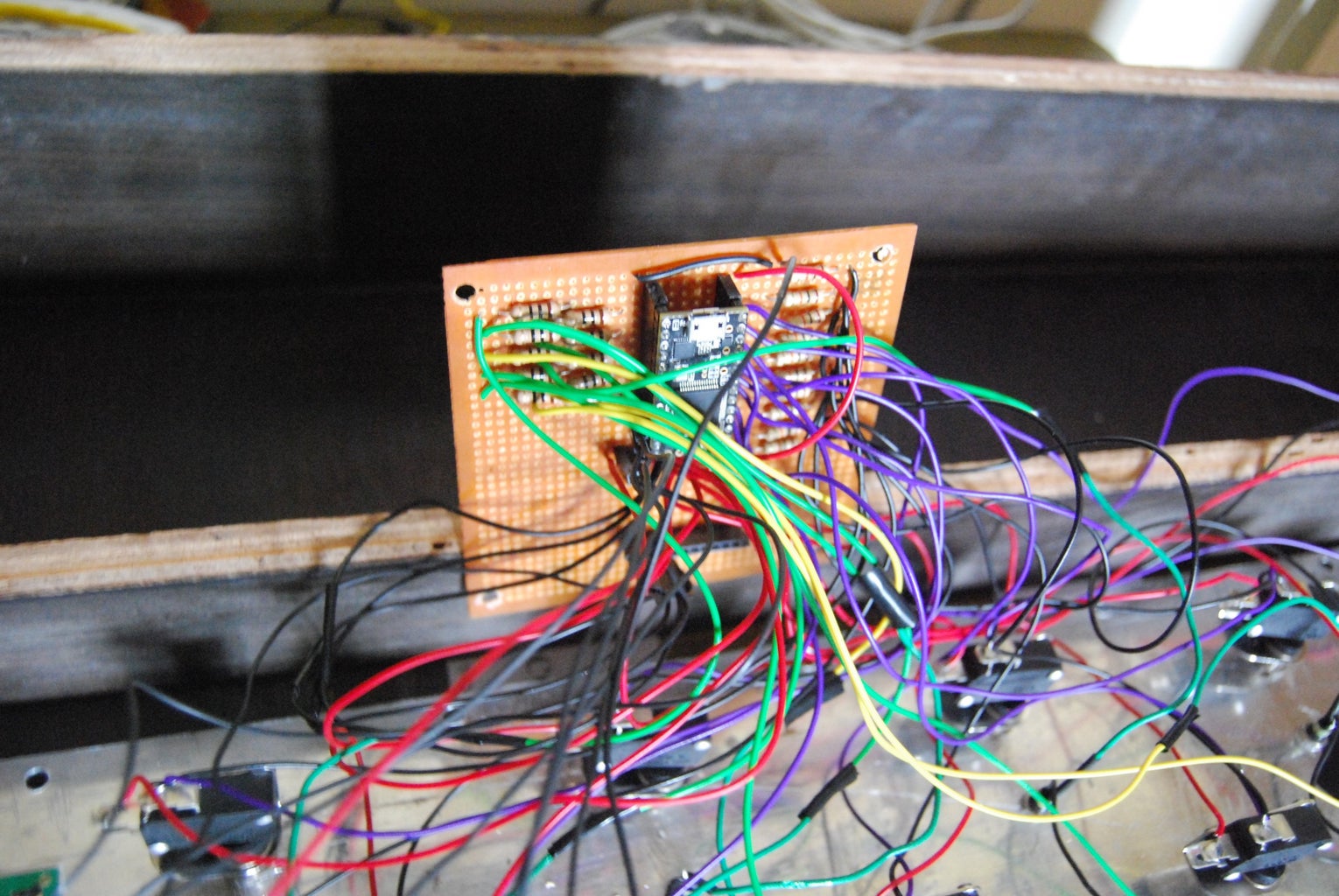
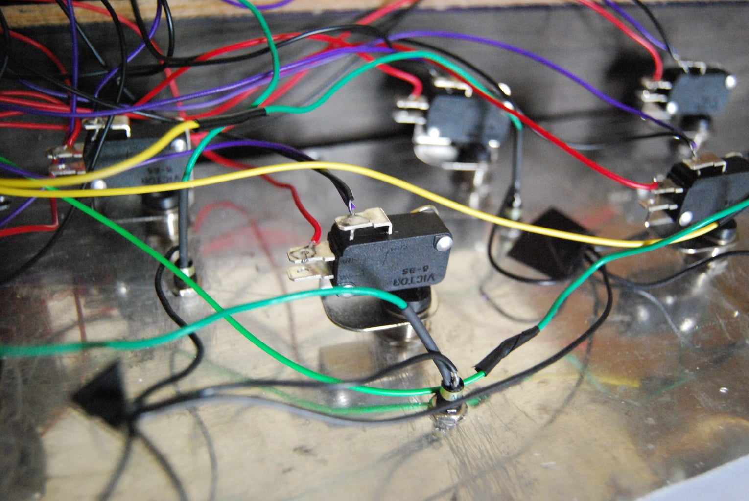
The circuit design is fairly simple and straightforward. I haven't provided a circuit diagram for the entire build, but it should be easily deducible from the diagram included for prototyping. It's very easy to build it, but make sure to manage the wires neatly, because there are going to be a lot of them, and it could get messy ! Also best practice dictates that you colour code the wires, red for +5V supply, black for ground, one colour just for the switch inputs, and one colour for the LED inputs, so that you can easily differentiate them and diagnose a problem if necessary.
Drill out a small hole for the USB cable. For this, mount the perf board onto the wooden base, and then mark out a section in the wood, where the cable needs to come through. My slot grew wider due to measuring inaccuracies, but I just filled it with some M-seal to make the extension sturdy.
This is it, time to upload a fully functional sketch(code) into your arduino. There are two sketches you can download. The first one is the sketch to my midi controller. Choose this, if you're building something similar to what I've build. The second sketch is a generic midi controller sketch which can extend many midi functionalities through USB, such as control change messages, note on/off values with velocity, continuous control change messages for analog pots, and even for touch sensitive pins.
Step 5: 4) Operation


Now that your controller is fully functional, let's get to the task at hand,
programming it to control our software looper, Mobius. I have used Reaper as my DAW host software, your's maybe different, but the same steps apply.
1) First, go to Options > Preferences. Go under MIDI device. Enable your arduino device's input, output and control. Mine shows up as Teensy MIDI.
2) Create a track, and load the VST Mobius.
3) Create another track, this is going to be your instrument track. Arm the record button. It can either be an audio track for recording guitar, or a midi track for recording a sampler or a VSTi. We need to route the output of this to Mobius. Click on the I/O button and drag it on to the Mobius track. Click on I/O button again and disable master/parent send. We do this, so that we hear audio just from the Mobius track, and not from the instrument track; the instrument track is dummy, just for capturing input.
4) Create another track, this is going to be our control track. Drop down the input selection to this channel, select 'Input: MIDI' -> 'Teensy MIDI' -> 'All channels'. This makes it a midi track. Enable Record Arm and enable Monitoring. This is important. Now drag the I/O button on to the Mobius track.
5) Open up the Mobius VST. Go to 'Configuration' -> 'Midi devices'. Select your midi device from Plugin Input Device and Plugin Output Device.
6) Now we need to map the buttons to a specified function. Go to 'Configuration' -> 'Midi Control'. Select a function you like, say Record, check the Midi Capture box. Press a button on your MIDI controller that you want to assigned. There should be corresponding parameters that should be displayed, something like 'Channel 1 Note 67'. Press the 'New' button to finalize the assignment.
This is how my buttons are assigned:
- Record
- Overdub
- Next Track
- Previous Track
- Reverse
- Mute (current track)
- Global Mute
- Global Reset
- Undo
- Redo
This is the layout that I'm comfortable with, you can assign other functions where you see fit.
You should be ready to go. Give it a try and spend some time to figure out the software's features and details, it has a learning curve.
Step 6: Concluding...
There you go, a satisfying build if you're an amateur DIY enthusiast. If you've got any questions whatsoever, just post a comment below, and I'll be sure to answer your queries. Below is a video of a demonstration of the midi footswitch, of me playing Sigur Ros's Hoppipolla, showing the core features of Mobius.
Also, it would be great if you can check out my Soundcloud page. I post a lot of my tracks there, all free to download, ranging from Post-rock and acoustic to progressive.
http://www.soundcloud.com/thrifleganger
Happy surfing !

Participated in the
Teach It! Contest Sponsored by Dremel

Participated in the
Tech Contest


