

Introduction: Temperature Sensor (Arduino)


This project is perfect for intermediate and beginner hobbyists. The setup is very simple. There is a chip named LM35 (link for additional explanation) that allows the Arduino to determine the temperature of the surrounding.
Supplies
1) 1 x Arduino nano/Arduino Uno + Connecting cable
2) 5cm x 5cm Perfboard or a small breadboard
3) 20 x jumper cables or wires
4) 1 x 16x2 LCD screen
5) 1 x 100K or 250K potentiometer
6) 1 x 9V battery + connector clip
Step 1: Designing and Understanding the Circuitry


The chip, LM 35, works on the principle that for every 1°C increase in the surrounding temperature the voltage outputted by the "out" pin of the LM 35 increases by 10mV. The linear relationship starts at 0°C. For example, if the temperature is 25°C the voltage outputted by the "out" pin would be 25 * 10mV = 250mV or 0.25V.
The Arduino can read the voltage level being outputted from the "out" pin when it is connected to one of the Arduino's analog pin. The function in the Arduino is analogRead. After receiving information about the voltage being outputted by the LM 35, the Arduino can perform a couple of simple calculations to finally get a value in celsius.
Step 2: Planning the Construction of the Circuitry

There are a couple of options on how to put together the circuit.
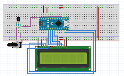
1) For people getting into electronics, I would recommend using the breadboard to build the circuit. It is a lot less messy than soldering, and it will be easier to debug because the wires can be adjusted easily. Follow the connections shown on the fritzing images.
2) For more experienced individuals, try out using soldering the circuit onto the breadboard. It will be more permanent and last longer. Read and follow the schematic for guidance.
3) Finally, you can also order a pre-made PCB from SEEED. All you would have to do it solder the components on. The necessary Gerber file is attached in the step. Here is a link to a google drive folder with the zipped Gerber file: https://drive.google.com/open?id=1STA7w9n3H7GhXtXTsLncc1apX-O-Hubv
Step 3: Soldering the LCD Leads
This step is necessary only if you are building the breadboard or perf board version of the circuit
I would recommend to solder leads onto the LCD as this will give you flexibility when you are trying to insert the 16x2 LCD into the User interface panel. Additionally, it will be easier to more securely connect the LCD to the Arduino pins.
Tips for soldering with pads:
Heat up the joint by placing the soldering iron on top of the contact point between the lead's pin and pad
Wait for about 5-8 seconds until the join is heated up
Feed the soldering write onto the pad. It should be near the contact point but not int
Step 4: Connecting the LCD to the Arduino


Pins 2,3,4,5 of the Arduino connect to pins 14,13,12,11 of the LCD, respectively, when counting from left to right.
Pins 1,5, and 16 of the LCD connect to ground
Pins 2 and 15 of the LCD connect to +5V
Pins 4 and 6 of the LCD connect to pins 12 and 11 of the Arduino respectively.
Pin 3 of the LCD is connected to +5V through a 100K or 250K potentiometer.
Pins 7, 8, 9, and 10 of the LCD are not connected to anything
Step 5: Connecting the LM 35 to the Arduino

When you make the flat side of the LM 35 face you the pins moving from left to right are 1, 2, and 3.
Pin 1 is connected to the power source. It works for any voltage between 4V and 20V
Pin 2 is the output pin. This is the pin that changes value with a change in temperature. Pin 2 is connected to pin A0 (Analog pin 0) in the Arduino.
Pin 3 is connected to ground. This is the negative or black side of the battery. This is also known as the 0V rail.
Step 6: Uploading the Code

Code is easy to follow. There are comments in the code itself to make it easier to understand
You can find a donwload link for the code here:
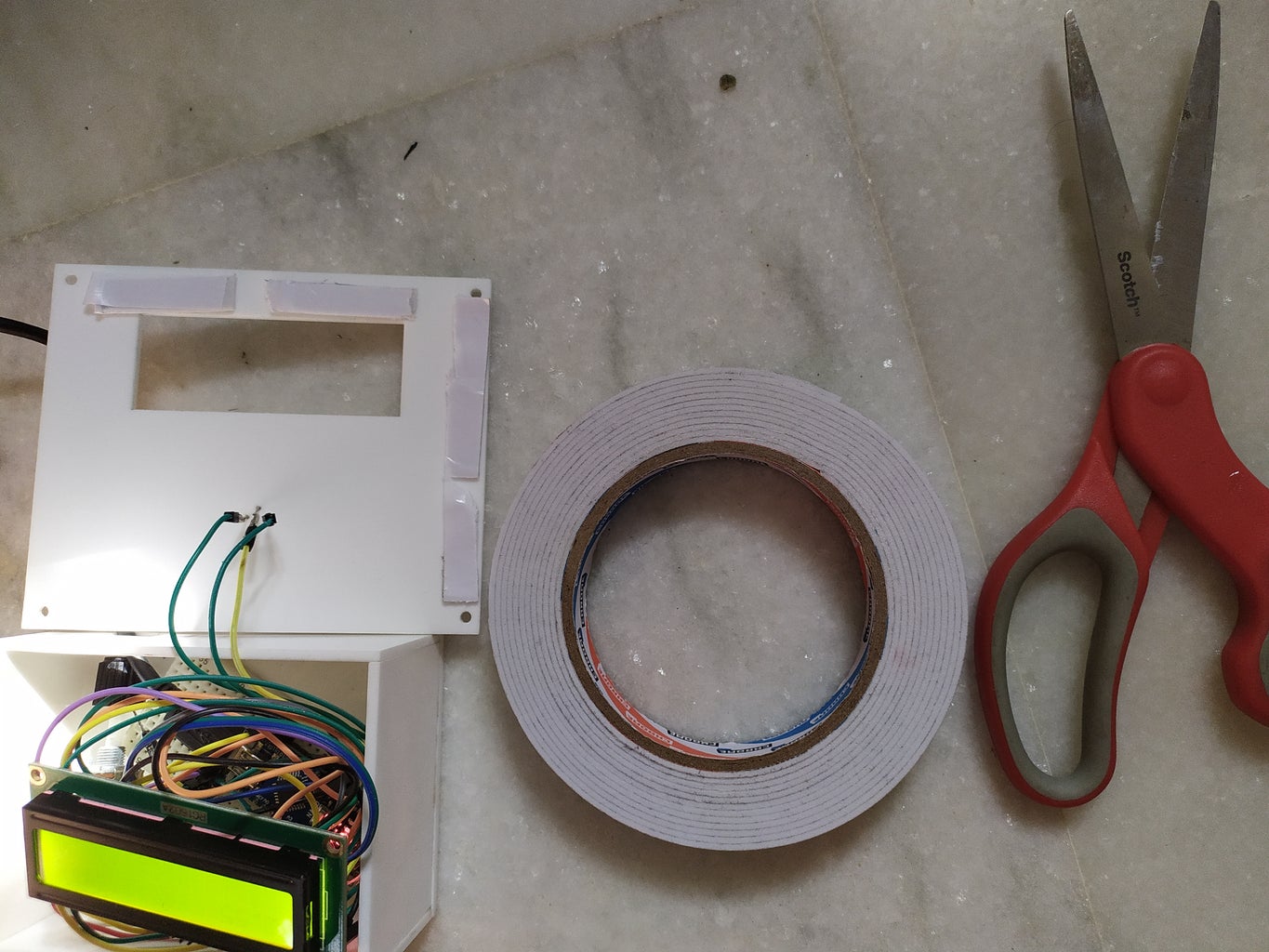
Step 7: Building the Housing

1) You can any old plastic case for its casing. Using a hot knife to cut out the slots for the LCD and button.
2) Additionally, you can check out my account for another instructable where I describe how to build a box out of laser cut acrylic. You will be able to find an SVG file for the laser cutter. https://www.instructables.com/id/Laser-Cut-Acrylic...
3) Finally, you can just leave the circuit without a casing. It will be easy to repair and modify.
Step 8: Testing the Temperature Sensor
As you can see the temperature shown increases once I put my hand on the sensor. It is relatively accurate if you want to know the day's temperature.


