

Introduction: Tests of LED and Various Light Sensors


Two circuits I was making, a proximity sensor and a sun tracker, weren’t working as expected, and so I decided to test the sensitivity of the light sensors these circuits used. On researching the subject, I was surprised that LEDs could be used as light sensors and that there are so many types of sensors for detecting light: photodiodes, solar cells, light dependent resistors (LDRs), and infrared (IR) phototransistors. My curiosity got the better of me and I decided to test them all.
I measured the voltage generated by each sensor from different light sources: sunlight, 100 watt incandescent light bulb, IR emitter, and two types of IR remote controls.
The IR emitter was connected to 3 AA batteries (4.5 volts) thru a 220 ohm resistor. The light would be brighter if the resistor had a lower value, but I wanted to be cautious after burning an emitter out. The purpose of the tests was to compare different sensors, and not to determine how bright an emitter could shine. That’s an experiment for the future.
Infrared light is invisible to the human eye, but the emitter had a barely visible red glow when lit. The IR light can be seen in the screen of a digital camera.
PARTS
- LEDs: a pack of 3mm and 5mm LEDs of various colors
- Photodiode: BPW34, suitable for visible and near infrared light
- Solar cell: from a very cheap solar garden lamp
- Light dependent resistor (LDR): 7mm diameter, 300 ohms light resistance and 10M dark
- Infrared (IR) detector #1: Knight Lites KID-7404 5mm (phototransistor)
- Infrared (IR) detector #2: 5mm (phototransistor), Radio Shack catalog #2760142 contains both a detector and an emitter. Comments on the Internet suggest that the detector in some of these packs is a transistor but in other packs it’s a photodiode, even though the description on both packs states “phototransistor” and the catalog number is the same.
- Sunlight: not very strong in late December at our latitude of almost 44 degrees North. A quick calculation shows the sun was only about 23 degrees above the horizon at noon.
- 100 watt frosted, incandescent, 120 volt, light bulb
- Infrared (IR) emitter #1: 5mm, Radio Shack catalog #2760143
- Infrared (IR) emitter #2: 5mm, Radio Shack catalog #2760142
- TV remote control
- LEGO Mindstorms EV3 IR beacon remote control
- Resistors (values in ohms): 150, 220, 680, 2.2K, 5K, 10K, 47K, 330K
- 3 - AA batteries and a battery holder
- Toilet paper roll
TOOLS
- Digital multimeter
- Utility knife or scissors
- Electrical tape
- Jumper wires with alligator clips
- Breadboard (optional) with jumper wires
- Digital camera if you want to see whether an IR emitter is working
The breadboard is optional, but it makes the job easier and faster. In the photo above, positive 4.5 volts from the battery holder can be supplied to the red row of holes along the length of the breadboard, and the negative side of the batteries to the blue row. The holes in each long row are connected together by metal strips under the board. The various LEDs and light sensors are plugged into different 5-hole rows. The 5 holes in each row are connected underneath. One side of all the resistors is plugged into one 5-row, and the other ends are in different 5-rows. This arrangement allows an LED or light sensor to be connected to any resistor and to power as needed.
Step 1: VOLTAGE DROP ACROSS LEDs


My first step was to measure the voltage drop across different colors of LEDs, with a variety of series resistors to limit the current.
LEDs have a long lead (the anode) which connects to the resistor and then the positive side of the battery, and the short lead (the cathode) goes to the negative side. The cathode may also be identified by a small flat part on the brim of its hat-shaped package.
Two photos show the connections for the green LED for one of the tests. An orange jumper is between the anode of the LED and the 5-hole row of the resistors. One photo shows a black wire from the cathode of the LED to the long negative row, and a red jumper from one of the resistors to the red positive row. The longer red and black wires go left to the battery holder. The voltmeter leads touch the LED leads. In the second photo of the breadboard, instead of using these long rows, I found it easier to supply the power directly to the parts for most of the tests by using wires with alligator clips.
Voltage Drop Across Each LED
3mm red3mm green5mm red5mm greenwhite
150 ohm resistor (about 15 mA) _ 2.24 _ _ _ 2.18 _ _ _ 2.28 _ _ _2.18 _ _ _2.05
220 ohm resistor (about 10.5 mA) 2.14 _ _ _ 2.11 _ _ _ 2.16 _ _ _2.11 _ _ _2.01
2.2K ohm resistor (about 1.2 mA) 1.86 _ _ _ 1.88 _ _ _ 1.86 _ _ _ 1.88 _ _ _1.87
As can be seen, the voltage was fairly similar for all LED and resistor combinations. The 2.2K ohm resistor reduced the current so much that the LEDs barely glowed.
The white LED looks clear with no voltage applied, but it glowed yellow (not white) with each resistor.
Step 2: LEDs AS a LIGHT SENSORS


The following Wikipedia article states that LEDs can be used as light sensors.
https://en.wikipedia.org/wiki/LED_circuit
Although the LEDs are fairly directional, I found that it’s important to wrap a small piece of electrical tape around a LED before measuring its voltage indoors, in order to shield it from the room lights (or, turn off the room lights). This made them even more directional. They had to be pointed right at the light sources to get the highest reading. Connecting my voltmeter to each LED as in the first photo, I obtained the following readings with different light sources.
Voltage Produced by Each LED
3mm red3mm green5mm red5mm greenwhite
Sunlight at noon _ _ _ _ _ _ _ _ 0.02 _ _ _1.56 _ _ _ _0.03 _ _ _1.58 _ _ _1.73
Cloudy day _ _ _ _ _ _ _ _ _ _ _ 0.00 _ _ _0.51 _ _ _ _0.00 _ _ _0.99 _ _ _1.35
Light bulb, 6 inches away _ _ _ 0.00 _ _ _0.12 _ _ _ _0.00 _ _ _0.20 _ _ _1.24
Light bulb, 12 inches away_ _ _0.00 _ _ _0.03 _ _ _ _0.00 _ _ _0.06 _ _ _0.49
Light bulb, 24 inches away_ _ _0.00 _ _ _0.01 _ _ _ _0.00 _ _ _0.02 _ _ _0.13
IR emitter, TV remote, 12 in._ _ 0.00 _ _ _0.00 _ _ _ _0.00 _ _ _0.00 _ _ _0.00
It's interesting that the green LEDs produced almost as much voltage as the white LED in sunlight, but were much less sensitive to the incandescent light bulb. I repeated the measurements to make sure they were correct.
The above method of using a photodiode is called the “photovoltaic mode” in the following Wikipedia article:
https://en.wikipedia.org/wiki/Photodiode
Another method is the “photoconductive mode.” A “reverse bias” is applied to the photodiode by connecting the batteries in the opposite polarity to step #1. Here, the short lead (cathode) goes to the positive of the battery, and the long lead (anode) goes to the resistor, which goes to the negative of the battery. The voltage is measured across the resistor, whose value needs to be quite a bit higher than that used in step #1.
A photo of the breadboard shows an orange jumper between the anode of the LED and the 5-hole row of the other group of resistors (the ones with higher values). The cathode goes to +4.5 volts, and the resistor goes to the negative side of the batteries. The red and black power wires go left to the battery holder. The voltmeter leads go across the resistor, using wires with alligator clips. This allows the breadboard to be moved easily to aim the LED at the light sources at different distances.
The voltages I got were too low to be useful. I tried several resistors and got the best results from a really high value. With a resistor of 330K ohms the white LED had .03 volts when 6 inches from the light bulb, and the 5 mm green one had .01 volts.
Step 3: PHOTODIODE

A photodiode converts light into electricity. I repeated the tests of Step #2 with the DPW34 photodiode. The pins are the proper size to fit a breadboard. There’s a line underneath the body, that indicates the pin producing the positive voltage. This pin connects to the resistor for the tests of the reverse bias method (photoconductive mode).
It was not as directional as the LEDs in the previous tests. Its specifications state it has a +-65 degree angle of half sensitivity. It was very tricky to get a very narrow piece of electrical tape around it to shield it from the room light.
Photodiode _ _ With Reverse Bias
Alone _ _ _ 10K _ _ 47K _ _ 330K
Sunlight at noon _ _ _ _ _ _ _ _ _ 0.60 _ _ _ 5.02 _ _ 5.04 _ _ 5.05
Light bulb, 6 inches away _ _ _ _0.46 _ _ _ 2.34 _ _ 4.88 _ _ 4.92
Light bulb, 12 inches away _ _ _ 0.41 _ _ _ 0.72 _ _ 3.38 _ _ 4.86
Light bulb, 24 inches away _ _ _ 0.36 _ _ _ 0.24 _ _ 1.13 _ _ 4.79
IR emitter #1, 12 inches away_ _0.27 _ _ _ 0.01 _ _ 0.06 _ _ 0.47
IR emitter #2, 12 inches away_ _0.28 _ _ _ 0.03 _ _ 0.15 _ _ 1.03
TV remote, 12 inches away _ _ _ 0.03 _ _ _ 0.01 _ _ 0.03 _ _ 0.13
LEGO IR beacon, 12 in. away _ _0.00 _ _ _ 0.00 _ _ 0.00 _ _ 0.01
Held under the work table_ _ _ _ 0.08 _ _ _ 0.00 _ _ 0.00 _ _ 0.03
Surprisingly, there was a small voltage when the photodiode was in the dark, held touching the underneath of the work table. I found the answer in the Wikipedia article on photodiodes, which states that “A small amount of current is also produced when no light is present.”
The voltages for the IR emitters, TV remote and LEGO IR beacon in the chart above are the additional voltages after subtracting the dark voltage. I measured these under the table.
An interesting observation is that the voltage measured across the resistor in photoconductive mode, with a bright light, is higher than the voltage of the batteries. I measured the voltage across the photodiode in this test and realized that the voltage generated by the photodiode makes this happen.
Another surprise is that the voltages of the green and white LEDs were much higher than the photodiode alone, in daylight.
Step 4: SOLAR CELL


A solar cell also converts light into electricity. I bought a very cheap solar garden lamp, took it apart, snipped the wires of the solar cell, and repeated the tests of Step #3. The innards of the lamp contained a small circuit, which looks interesting, but that’s something to be figured out some other time. The circuit board showed which wire was positive (the white one) and which was negative (the black one). The other two wires go to the re-chargeable battery.
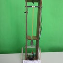
The solar cell was not very directional. I shielded it from the room light with half of a toilet paper roll, after slitting the roll lengthwise because it was a little bit too small, and covering the gap with electrical tape. A photo shows this above. Using wires with alligator clips, the voltmeter leads go to the wires of the solar cell,. This allows the solar cell to be moved easily to aim the LED at the light sources at different distances.
Solar Cell _ _ _ _ With Reverse Bias
Alone _ _ _ 680 _ _ 10K _ _ 47K _ _ 330K
Sunlight at noon _ _ _ _ _ _ _ _ _ 2.60 _ _ _ 6.63 _ _ 7.13 _ _ 7.16 _ _ 7.18
Light bulb, 6 inches away _ _ _ _2.19 _ _ _ 0.43 _ _ 5.48 _ _ 6.57 _ _ 6.62
Light bulb, 12 inches away _ _ _ 1.98 _ _ _ 0.13 _ _ 1.76 _ _ 6.11 _ _ 6.43
Light bulb, 24 inches away _ _ _ 1.87 _ _ _ 0.05 _ _ 0.58 _ _ 2.34 _ _ 6.21
IR emitters, TV remote, etc. _ _ _0.00 _ _ _ 0.00 _ _ 0.00 _ _ 0.00 _ _ 0.00
Held under the work table _ _ _ _0.00 _ _ _ 0.01 _ _ 0.18 _ _ 0.66 _ _ 1.81
The voltages for the IR emitters, TV remote and LEGO IR beacon in the chart above are the additional voltages after subtracting the dark voltage. I measured these under the table.
Although the Wikipedia article on photodiodes states that “... a traditional solar cell is just a large area photodiode,” there were some differences in the measurements. The solar cell doesn’t produce a voltage in the dark. It doesn’t see infrared light. And for visible light, without reverse bias, it produces approximately four times the voltage of the photodiode I tested.
Step 5: LIGHT DEPENDENT RESISTOR (LDR)


The resistance of a light dependent resistor (LDR) decreases with an increased amount of light. I measured the resistance of the LDR, and also measured the voltage across a 5K ohm resistor connected in series with the LDR to the batteries. Again, electrical tape should be wrapped around it for the indoor tests.
LDR_ _ _ V. Across R
Resistance _ In Circuit
Sunlight at noon _ _ _ _ _ _ _ _ 74 ohms _ _ _ 4.36 v
Light bulb, 6 inches away _ _ 497 ohms _ _ _ 4.02 v
Light bulb, 12 inches away _ _ 1.02 K _ _ _ _ _3.66 v
Light bulb, 24 inches away _ _ 1.87 K _ _ _ _ _3.21 v
IR emitter, TV remote, 12 in._ _> 2 M _ _ _ _ _ 0.03 v
Held under the work table_ _ _> 2 M _ _ _ _ _ 0.03 v
The meter doesn't display resistance above 2 megohms.
Step 6: INFRARED (IR) EMITTERS

I repeated the tests with the IR emitters, since they are LEDs and should be able to sense light in the same way as the LEDs did in Step #2. But I didn’t try the reverse bias method. Again, electrical tape around it.
Emitter #1 _ _ _ Emitter #2
Sunlight at noon _ _ _ _ _ _ _ _ _ _ _ _ 0.95 _ _ _ _ _ _ 1.17
Light bulb, 6 inches away _ _ _ _ _ _ _ 0.83 _ _ _ _ _ _ 1.02
Light bulb, 12 inches away_ _ _ _ _ _ _0.80 _ _ _ _ _ _ 0.97
Light bulb, 24 inches away_ _ _ _ _ _ _0.75 _ _ _ _ _ _ 0.90
IR emitter #1, 12 inches away _ _ _ _ _N/A _ _ _ _ _ _ _0.01
IR emitter #2, 12 inches away _ _ _ _ _0.65 _ _ _ _ _ _ _N/A
TV remote, 12 inches away _ _ _ _ _ _ 0.24 _ _ _ _ _ _ _0.00
LEGO IR beacon, 12 in. away_ _ _ _ _ 0.03 _ _ _ _ _ _ _0.00
Held under the work table _ _ _ _ _ _ _0.00 _ _ _ _ _ _ _0.00
Interesting that emitter #2 was much less sensitive to IR light than emitter #1.
Step 7: INFRARED (IR) DETECTORS (PHOTOTRANSISTORS)


A phototransistor amplifies the light shining on it, and may be connected in either a common emitter configuration (with a resistor in series between the collector and the positive power) or common collector (with a resistor between the emitter and the negative side). Details are in this website:
The website also states that the circuit can operate in one of two modes. With a large-value resistor it is in switch mode, and the output voltage is very low with little or no light and switches to high with some or a lot of light. With a small resistor it is in active mode, and the output voltage varies roughly proportionally with the amount of light.
I used the common collector configuration in order to get voltages that increase when light is detected. The packaging of the detector stated that the collector is the short lead and has a small flat part on the brim of its hat-shaped package. It goes to the positive terminal of the battery. The emitter is the long lead. It goes to the resistor, which goes to the negative terminal. (On the Internet, there are some websites that show the opposite for the short and long leads of a phototransistor.)
I also measured the voltage just across the phototransistors themselves without any power being applied. These are IR detectors, but they also pick up room light and need to be shielded by wrapping electrical tape around them.
The results for detector #1 (Knight Lites KID-7404):
Detector _ _ _ _ Common Collector
Alone _ _ _ 680 _ _ 10K _ _ 47K _ _ 330K
Sunlight at noon _ _ _ _ _ _ _ _ _ 0.00 _ _ _ 4.39 _ _ 4.44 _ _ 4.45 _ _ 4.47
Light bulb, 6 inches away _ _ _ _0.00 _ _ _ 4.32 _ _ 4.43 _ _ 4.44 _ _ 4.47
Light bulb, 12 inches away _ _ _ 0.00 _ _ _ 4.27 _ _ 4.43 _ _ 4.43 _ _ 4.47
Light bulb, 24 inches away _ _ _ 0.00 _ _ _ 4.08 _ _ 4.40 _ _ 4.42 _ _ 4.46
IR emitter #1, 12 inches away_ _0.00 _ _ _ 0.46 _ _ 2.10 _ _ 4.27 _ _ 4.32
IR emitter #2, 12 inches away_ _0.00 _ _ _ 1.13 _ _ 4.31 _ _ 4.37 _ _ 4.40
TV remote, 12 inches away _ _ _ 0.00 _ _ _ 0.08 _ _ 1.23 _ _ 1.84 _ _ 2.40
LEGO IR beacon, 12 in. away _ _0.00 _ _ _ 0.01 _ _ 0.22 _ _ 0.41 _ _ 0.51
Held under the work table_ _ _ _ 0.00 _ _ _ 0.00 _ _ 0.00 _ _ 0.00 _ _ 0.03
The results for detector #2 (Radio Shack catalog #2760142):
Detector _ _ _ _ Common Collector
Alone _ _ _ 680 _ _ 10K _ _ 47K _ _ 330K
Sunlight at noon _ _ _ _ _ _ _ _ _ 0.60 _ _ _ 2.75 _ _ 5.02 _ _ 5.05 _ _ 5.06
Light bulb, 6 inches away _ _ _ _0.43 _ _ _ 0.23 _ _ 3.78 _ _ 4.83 _ _ 4.87
Light bulb, 12 inches away _ _ _ 0.40 _ _ _ 0.07 _ _ 1.09 _ _ 4.64 _ _ 4.80
Light bulb, 24 inches away _ _ _ 0.36 _ _ _ 0.02 _ _ 0.31 _ _ 1.87 _ _ 4.74
IR emitter #1, 12 inches away_ _0.24 _ _ _ 0.00 _ _ 0.01 _ _ 0.06 _ _ 0.54
IR emitter #2, 12 inches away_ _0.28 _ _ _ 0.00 _ _ 0.04 _ _ 0.19 _ _ 1.56
TV remote, 12 inches away _ _ _ 0.11 _ _ _ 0.00 _ _ 0.01 _ _ 0.04 _ _ 0.24
LEGO IR beacon, 12 in. away _ _0.02 _ _ _ 0.00 _ _ 0.00 _ _ 0.00 _ _ 0.06
Held under the work table_ _ _ _ 0.00 _ _ _ 0.00 _ _ 0.00 _ _ 0.00 _ _ 0.01
In the common collector configuration, detector #1 was far more sensitive at low light levels. Measuring just the detectors, however, detector #1 showed zero voltage for all the light sources but detector #2 had readings similar to the photodiode. In fact, the voltages for detector #2 in the common collector configuration were roughly similar to the photodiode with reverse bias in Step #2. Maybe detector #2 is a photodiode even though the package states phototransistor?
Emitter #2 produces more IR light than emitter #1.
Step 8: CONCLUSIONS
These were very interesting tests. Some overall observations:
All the LEDs were very directional, even without the electrical tape around them. The photodiode was less directional and the solar cell even less. The IR emitters and detectors were also very directional.
With no reverse bias, the green and the white LEDs produced more than twice the voltage of the photodiode in sunlight, but much less than the photodiode in low light. With reverse bias, the LEDs did almost nothing, while the photodiode gave very good results.
The solar cell produced a much higher voltage than the photodiode for visible light, but it was useless in infrared light.
As expected, the IR phototransistor was much more sensitive than the photodiode in reverse bias mode, especially in low light and with infrared.
The Radio Shack IR detector behaved like a photodiode, not the phototransistor it was documented on the package.
The results may depend to some degree on the specific parts I used. Other LEDs, photodiodes, etc. may produce somewhat different results. Anyway, I learned a lot from doing this project, and I hope the information is useful to you folks.


