

Introduction: The Allen Hydrautomat, a Working Paint Tin Model.


A silent system of raising water patented in 1926 by Thomas Gaskell Allen, was alleged to have an efficiency of 80% of the pressure water used, a more efficient device than the hydraulic ram pump at the cost of greater parts and complexity.
Sadly, this wonderful device seems to have faded into obscurity over the years and so I have attempted to recreate a working model with the original principles involved.
Step 1: A Brief Working


Referencing the patent diagram, the system used the pressure of the inrush of water into a closed chamber called the operating chamber A, to pump water in the closed chambers C and Cx up to the next level.
Then the outflow of water in chamber A creates a partial vacuum which is used to draw up water from the open chambers G and D into the now empty C and Cx.
A is connected to the closed chambers C and Cx via an air duct as well as to open chamber G via the water inlet to A.
Prior to the working of the pump, closed chambers C and Cx should be manually filled with water as a requirement for initial operation.
The original device used different lengths of syphon tubing to prevent water from being sucked down from an upper level, but the method of operation escapes me and so I have improvised and installed a check valve on the tops of the inlet and outlet tubes as my primary method of avoiding reverse flow.
The 2nd diagram is my view of the sequence of events, bear in mind that the water source will keep the inlet tin on level 2 constantly full.
- The initial stage, new device all tins/ containers are empty, all open tins to be filled is the starting requirement.
- The first pumping cycle, default inlet valve position is open with foot valve closed, operating chamber begins filling pressurizing the empty closed tins which should result in bubbling in the open tin on level 4.
- The foot valve is triggered with the linked inlet valve closing, creating a vacuum in the operating chamber and the first suction cycle draws up water from the open tins into the closed tins.
- The second pumping cycle occurs once the trigger mechanism empties and resets, closing the foot valve and opening the linked inlet valve, causing the operating chamber to fill, once again pressurizing the closed tins. Now the first water output should be seen from the upper pumping stage.
- The foot valve opens starting the suction cycle once again.
Step 2: The Frame


The frame was made out of 17mm bamboo uprights and 4mm bamboo skewers for the platforms. My hypothetical design head of water is 400mm and the operating chamber is placed midway between the upper and lower levels.
- The 1st level is the operating chamber at 200mm.
- The 2nd level is 200mm above 1, being for the 1st open chamber which feeds the operating chamber and the 1st closed pump chamber C.
- The 3rd level is 160mm above 2 and holds closed pump chamber 1.
- The 4th level is at another 160mm and holds an intermediate open chamber.
- The 5th level is at another 160mm and holds closed pump chamber 2.
The number of pumping levels is unlimited but must follow the 2 design rules, namely that the operating chamber volume cannot be less than the combined closed chamber volumes and that each pumping stage height cannot exceed the working head height, which in my version is 200mm.
I decided to design my model conservatively with a pumping stage height of 160mm which is also 80% of the working head height.
The bamboo skewers were tacked together with hot melt glue and then all joints were lashed with thread soaked in CA glue.
Each level platform was then glued into the main uprights, again using hot melt glue.
Step 3: The Check Valves


Generally a build would have started with the available valve hardware and then designed the containers around them. I went about it differently out of necessity, I had the containers and matching tubing so it was a matter of designing check valves to suit.
A single flare was formed on the 3/8 " copper tube which acts as the valve seat.
- The first version check valves were made from a rubber screwdriver bit holder with a piece of copper wire bent to function as the guide. The copper wire retaining method made it easy to bend to one side so as to slide the pipe into the wire guide for soldering, but the rubber proved too hard to seal properly.
For the 2nd version I added a soft silicone overlay in the form of a small section of a nipple from a baby’s bottle, but the silicone or latex had a tendency to catch on the seat rim and didnt always center properly.
The final version was a sliding fit brass tube with a small flare to retain an O ring with a section of a brass earth pin from an electrical plug soldered into the top of the brass tube.
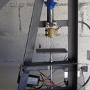
Step 4: The Operating Chamber / Release Valve


At the bottom on level 1 is the closed operating chamber, this is where the vacuum and pressure cycles are developed.
The outlet needs to be braced to provide a rigid seat for the swinging valve and also against the pressure of ejecting water. I have used 15mm dia pipe due to the greater force of the ejecting water as compared to that of the 3/8" tubing.
More on the trigger mechanism in the following steps.
Step 5: The Allen Trigger Mechanism


The trigger valve at the bottom of the operating container is the heart of the system, opening once the water inrush has reached the required height and at the same time closing the linked inlet valve in the open chamber above.
From the sole photo of the device certain educated guesses can be made, however the method of linking the trigger reservoir to the valve flap remains vague, keep in mind that the default position of the bottom valve is closed and the top inlet valve is open. It then follows that the trigger reservoir will descend as it fills with water from the trigger feed tube, and empty itself at the bottom of its stroke with the valve opening in the process.
The trigger tube can be seen to have an increase in diameter on the downward side, so logic would dictate that an open tube of a larger diameter than the trigger feed tube, rides freely up and down the trigger tube and releases its water load at the bottom of its travel via a hinged mechanism at its base.
An assumption is that the odd U shaped outlet before the valve flap was required to obtain clearance for the trigger mechanism.
The trigger water inlet tube peaks just under the water level of the open chamber above which will allow the water level in the operating chamber to actually rise up the air conducting pipe, thus ensuring greater possible vacuum and subsequent pressure cycles.
Step 6: My Plan a Trigger Mechanism


Plan A, although nice and shiny looking, didn't work, the reason being that the trigger reservoir was too heavy even while empty and the measly 12 grams of water inflow didnt weigh enough to tilt the valve open.
So its back to the drawing board for Plan B, a lighter PVC trigger pipe 20cm long that weighs under 40 grams when empty and carries a water load of 75grams.
Step 7: My Plan B Trigger Mechanism


Plan B has custom made end caps much lighter than commercial 25mm pvc stop ends, and it will be offset from the center line due to it being 20cm long.
First the fittings were soldered and then the copper pivot tube was wired to the end cap.
In use the valve didn't seal as well as it could have, due to the ferrule's hard rubber compound, so I added a softer overlay in the form of a finger cot.
I also made a plastic deflector shield in the form of a section of yoghurt tub, this triggers the opening mechanism much sooner as the pics indicate, producing a faster system vacuum rise.
Next I moved the trigger tube water entry to the back so as to be over the pivot point thereby reducing the swinging resistance of the previous method.
Finally the distance from the counter weight to the pivot was increased to 190mm over the previous version's 80mm, this coupled with the curved link to the rubber stopper creates a much greater seal force, in excess of 250grams.
Step 8: The Open Tin / Inlet Valve


This tin on the 2nd level feeds both the operating chamber below it as well as the 1st closed tin immediately above. It contains the inlet valve to regulate the operating chamber and a method of constant water supply.
- The first version check valve rubber was made from one of the screwdriver bit holders, a length of copper wire forms both the means of lifting and a way to guide it onto its seat. The top of the rubber was plugged with silicone sealant.
- Final version was a sliding fit brass tube with O ring seal.
- The pivot was made from 2 aluminium strips riveted together and clipped onto the tin rim.
- The 5mm dowel section was drilled for the paper clip hooks and axle.
Step 9: 1st Pumping Stage

This is the simple tin on level 3, the 1st closed tin which has the same body as the tin on the 5th level, just the lids differ.
Step 10: 2nd Open Tin


This was a tricky build because the lid for the below closed tin needs to be soldered to this input tube.
The inter tin copper tubes were offset from the center for obvious reasons( frame structure) which allowed them to be staggered on alternating levels to prevent inlet tubes from obstructing outlet tube valves.
The sequence of pics shows how the offset tube allowed tins to be rotated into place.
Naturally one could cut the copper tube and join with gas or other reinforced tubing once in place, at the risk of more leakage possibilities.
Step 11: 2nd Pumping and Final Stage


Details of the 2nd pumping stage on level 5, the air conduit and pump outlet soldered into the lid, and a water inlet from the open tin below, soldered into the can body.
The air conducting tube connects the closed tins of levels 3 and 5 to the operating chamber and were divided into 3 pieces for easier installation. An irrigation T piece was used with 8mm gas tubing to connect the 3 copper sections.
The plastic container on top is for diverting the output to a measuring jug when testing or a needy area of the lawn.
Step 12: Some Build Points


I found it easier to build from the top down after first making the check valves, mostly because I hadn’t worked out the operating chamber valve design at that stage, but it is easier to assemble the tower from the bottom up.
I studied the photo of the original device and copied the proportions of tin to pipe as closely as possible. I estimated that the tin diameter was approximately 11 to 12 times larger than the tubing diameter, hence my choice of 3/8" tubing throughout, baring the trigger feed tube, smaller was more economical and just meant the vacuum cycle would take longer to complete. Likewise the bottom outlet tube was increased to a slightly larger size for improved performance and my testing indicated 15mm would be more than adequate with 22mm too large.
Another problem, other than the tube kinking, showed up on the trigger tube flexi link to the PVC pipe, an air bleed hole was needed to allow the PVC tube to empty itself when it was in the down position. This leaks water as the PVC pipe starts filling which slows down the tube filling process. On the other hand it gives an indication of when the pipe is about to drop.
After much observing of the pvc tube and flexi link, I decided to adopt a slider tube system to minimise resistance. The slider tube yields a better air bleed system and isnt prone to tearing like a hole in the silicone tubing is.
Some figuring with moments about a beam equations yielded a theoretical counter weight of 45g which worked first time, yay for engineering science. That was after plenty calulating volumes of a cylinder and then actually measuring the PVC pipe filled with water. Turns out the theory was pretty close, 2g off, which is neither here nor there.
My main tool in addition to a hacksaw and pliers was the brake pipe flaring kit which also included a pipe cutter. It was during the project that I also bought a small tubing bender to make the work a bit neater.
Lastly, I found it easier to manage the bottom tin by soldering on the outlet tube to the down pipe elbow last of all.
Some Design Considerations.
The first rule of design is that the operating chamber volume cannot be less than the combined volume of the closed chambers.
The second rule of design is that each pumping stage height cannot exceed the initial working head height.
Although not exactly a design rule, but equally important, use rigid containers and piping where system vacuum and pressure are encountered. Plastic tends to flex too much, reducing the amount of working vacuum and pressure available.
Step 13: End Testing

Other than sealing problems in the first test, the 2nd test went fairly well, due to much fine tuning of the operating chamber and the linked supply valve over the kitchen sink. Initially there was a gurgling on the pressure stroke in the closed tins, meaning there was more pressure than water, which could also indicate a leaky valve on the inlet tubes to the closed tins.
After many mods on the trigger tube to extend the down time to increase system vacuum, it occurred to me that the pressure from the open tin would always be consistent as long as the water level was maintained near the top, but the vacuum in the vacuum cycle would diminish as the water in the operating chamber dropped down to a final equilibrium level.
In use 1.2 litres is flushed out the bottom valve in order to pump 225ml out of the top stage.
First video is a general top down view to capture all the goings on and the second one is a closer look at the operating chamber valve.


