

Introduction: The JClock


Hello, my name is James Hubbard and I created this clock that I call the jClock. It uses a ds1302 real time clock module that can keep time more precisely than the Arduino can. This is what you will need to build it:
1. Arduino Uno.
2. ds 1302 rtc (real time clock)
3. Temperature sensor model TMP36
4. Breadboard
5. LCD screen 16 by 2
6. Potentiometer (for the contrast of the screen)
7. 220 ohm resistor
Step 1: Connect the Power

Connect 5V on your arduino to one side of the power strip on your breadboard and connect ground to the other. Be careful to not short circuit.
Step 2: Connecting the Temperature Sensor

Place the temp sensor on the top of the breadboard, with, as shown in the picture, the flat side facing the arduino. The top pin goes to 5V on the breadboard, the middle pin goes to analog pin 0 on the arduino, and the bottom pin goes to ground on the breadboard.
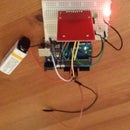
Step 3: Connecting the Time Module


The time module should look like the first picture. First, on the time module, connect VCC to 5V, and GND to ground on the breadboard. Then, connect clk to digital pin 6, dat to digital pin 7, and rst to digital pin 8 on the arduino as shown in the picture.
Step 4: Connecting the Potentiometer

Stick the potentiometer on the top of the breadboard too. I'm having you put everything on top of the breadboard because the screen will go on the bottom of the board. The top pin of the potentiometer goes to 5V, middle connect a wire to but don't do anything with it yet, and the bottom goes to ground.
Step 5: Connecting the LCD Screen

This is the most confusing step because it has a lot of wires. Stick the screen in the lower right corner of the breadboard. Starting at the bottom, pin 1 is the bottom pin and pin 16 is the top pin of the screen. Pin 1 goes to ground. Pin 2 goes to 5V. Next, connect the potentiometer to pin 3. Pin4 on the lcd goes to pin 12 on the arduino, likewise with pins 6 and 11. Pin 5 on the lcd goes to ground. We skip pins 7, 8, 9, and 10. Then pin 11 of the lcd connects to pin 5 on the arduino, likewise with pins 12 and 4, 13 and 3, and 2 and 14. Pin 15 connects to 5V with a 220 ohm resistor in between, and pin 16 goes to ground.
Step 6: The Code
The code file is below. Run it using arduino IDE.
Attachments


Participated in the
Microcontroller Contest


