

Introduction: The Ultimate USB Backup Pack


Need to keep your phone charged for a fortnight?
Commercially available USB battery packs are usually less than 10Ah capacity. This is fine if you need juice for a few days but what if you need it for a few weeks? In this instructable I describe how to build a 40.6Ah battery backup with dual USB outputs and voltage meter.
Step 1: Materials and Tools


Materials
- Lithium Ion cells, I used 7 5.8Ah cells in parallel to give a total of 40.6Ah
- Fuses, I used a 1A fuse for each cell and a 5A for the whole lot
- USB / solar / DC Lithium Ion charger from Adafruit http://www.adafruit.com/product/390
- 10k NTC thermistor
- A switch, I used this one https://www.adafruit.com/products/481
- A P- Channel Logic Level MOSFET I used a NDP6020P
- Two 3V to 5V 1A boost converters, mine were off eBay
- A double stacked USB header
- A LED bar graph mine had red, yellow and green bars and was a HDSP-4832
- A LM3914
- A 1k and a 2k trimpot
- 3 10k resistors
- A 1k resistor
- a piece of strip board PCB
- Some red and black wire
- Assorted tape, heat shrink and glue
- A case of some sort, I used an old leather writing case
Tools
- General electronic tools, soldering iron, wire strippers, ect
- General mechanical tools, screwdriver, craft knife, scissors, ect
- Multimeter
- Sewing needle and thread
- Lighter for heat shrink
A adjustable power supply, I used a LM2596 adjustable step down converter
Step 2: The Case


I used an old leather writing case. In order to prepare it for its upgrade I unpicked the stitching holding in the inside flap and the "pen holder" strip, leaving a blank inside.
Step 3: The Cells


Your cells can be as large or as small as you like. Mine are each 5.8Ah. They must however be rated for a 4.2v max voltage to be compatible with the charger.
Lithium ion cells are dangerous because they are full of nasty chemicals and can catch fire if you mistreat them. These cells are 25c rated meaning they can each discharge (25 * 5.8)145A - no problem. if you manage to short circuit one it will discharge even more. Once all 7 packs are in parallel the battery will be able to discharge 1015A, which is why fuses are required, 1A for each cell and 5A for the whole pack.
My Cells didn't have the polarity labeled so I used my multimeter to identify the positive pin and marked them with a red sharpie.
I then soldered on a positive and negative lead with a 1A fuse inline. To start with I had great trouble getting the battery tabs hot enough to solder due to the battery dissipating the heat, I found that if I cut a strip most of the way off, the reduced area allowed me to solder on the wire more easily.
I put a length of heat shrink over each fuse for insulation.
I then put tape over the ends to insulate the cells and taped round them and the wires for strain relief.
To fit them in to the case I laid them out and drew round them, and then cut through the cardboard "structure" of the case to provide a recess. The case had foam which I left intact.
I used tape to hold the cells in place
Step 4: The Ada Fruit Lipo Charger


https://www.adafruit.com/products/390
Adafruit has an extremely good tutorial on using this charger here https://learn.adafruit.com/usb-dc-and-solar-lipoly...
The steps I took to prepare the charger were:
Electrical
- Desolder the PROG and THERM SMD resistors.
- Solder the 1k resistor in the PROG space. This sets the charging current to 1A rather than the 0.5A default.
- Solder the 10k NTC thermistor to the THERM pins, which needs to measure the temperature of your Lipo cell/cells so you may have to extend it a bit. I put some heat shrink on the leads to allow them to be bent over to the nearest cell.
- Solder the provided capacitor in place. I bent mine over because of the confined space it would have to fit into.
- After a test fit I decided to de-solder the DC barrel jack. I discovered you have to solder a jumper on the pads along the right hand side of the jack to charge from using the USB port.
- Solder the provided connector to the battery with the 5A fuse in line.
Mechanical
- Do a test fit to work out where your going to locate the charger.
- Like I did for the cells I cut a recess in the case and taped the board down.
- Make sure your thermistor is in contact with a cell.
Test it, the charger should now charge. Plug in the battery and a USB cable and the power LED and the charging or done LED should light
Step 5: Voltage Meter Prototype


If you just want to build it and don't care how it works skip this step.
The voltage meter is a fairly simple LM3914 circuit. The LM3914 drives 10 on/off outputs as a voltage sense pin varies between two voltages.
Dave Jones has done a tutorial on using the LM3914 for almost the same purpose (a 2 cell pack rather than our single cell) I recommend you watch it.
After watching Dave's tutorial, I decided on some specs, 4.20v max voltage to 3.7v minimum with about 10ma LED current. I then followed through Dave's maths and came up with some resistor values(see second pic), assuming a divide by 2 resistor divider between the battery voltage and the sense pin.
I then built this up on a bread board, and tested it with a tiny lipo cell. I discovered the RH and RL voltages were a bit off due to the resister and chip tolerances. After some fiddling about I decided it would be easier to use a couple of trimmer pots.
I then added a P channel logic level mosfet and a pull-up resistor so that when the final line of the bar graph went out the mosfet was disabled, thereby acting as a low voltage cut off.
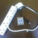
Step 6: Final Voltage Meter Circuit Construction


The circuit is extremely simple with only 1 chip, a LED bar graph, a mosfet, 2 trimmers and 3 resistors. I built it up on a piece of strip board PCB.
In order to get the red LED's at the bottom of the scale and the green at the top I had to put the LM3914 upside down on the bottom of the PCB. This in itself is not too tricky as long as you remember to cut the traces under it before you solder it in place.
Once the circuit is built you need to "tune" it. First power it from a 4.20v supply (I used an adjustable step down converter) and adjust the 2k trimmer(the bottom one in my pictures), which controls the offset from 0v of the scale, so that the top green LED just comes on.
Next set the input voltage to 3.8v and adjust the 1k trimmer, which is the range of the scale, so that the bottom red LED just goes off.
You may have to repeat the trimming several times as adjusting one pot affects the other slightly.
Step 7: Fitting Voltage Monitor and Switch


To fit the voltage monitor I cut a recess in the cardboard of the case as I did for the cells. I marked out the location of the LED bar and cut the foam away and sliced an X corner to corner in the leather.
This allowed me to push the display through with the flaps tucked back inside, I secured it with super glue.
I could then wire the switch, - as it has an LED it requires both a positive and negative lead. The wiring is very simple as one side of the switch goes to the positive load output on the Lipo charger and the other goes to the positive input of the voltage monitor and the LED. I then put a piece of heat shrink round the whole thing to insulate it.
Then connect the negative LED terminal of the switch and the negative wire from the voltage monitor to the negative load terminal of the Lipo charger.
You can now test that the LED bar graph and the LED inside the switch come on when you turn it on.
I then used a needle and thread to hold the switch in place.
Step 8: USB Output


I had planned to use a single DC-DC converter capable of stepping 3.8v-4.2v up to 5v at 2A (1A for each USB port). However, I couldn't find a low profile one so I ended up using two 1A converters.
I cut a hole for the USB port and cut through the cardboard and foam and cut an X in the leather and super glued it in place, as I had for the LED bar graph.
It was then a case of wiring up a DC-DC converter to each port. My converters were designed for USB so they had the resistors required to trick phones, (my android anyway Iphones might be more tricky), into thinking they are a wall adapter rather than a PC, thus enabling a faster charge.
The positive and negative leads coming from the voltage meter board can then be soldered to the positive and negative pads of the DC-DC converters.
Step 9: Finishing Off


I put a layer of tape over everything to hold it all in place.
I then packed out the case with some foam to stop things coming loose.
Step 10: USE IT!


This should keep my phone charged for at-least a fortnight, (I haven't been using it that long yet), and is fully solar capable. Just add a dc input port to the case and plug in a 6v panel to keep it topped up. Its probably not a good idea to leave the battery pack in direct sunlight as they don't like getting hot.
The only thing I would change is to use a thicker gauge wire. This is because drawing 1A gives a voltage drop over the wire of a few tenths of a volt and as the scale is a range of 0.5V (3.7v-4.2v) this can make the pack look flatter than it is until you stop drawing current.

Participated in the
Battery Powered Contest


