

Introduction: Thermostat Based on Arduino
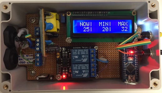


This time we are going to build a Thermostat based on Arduino, temperature sensor and relay.You can find on github
Step 1: Configuration

Whole configuration is stored in Config.h. You can change PINs controlling relays, reading temperature, thresholds or timings.
Step 2: Configuring Relays
Let's assume that we would like to have 3 relays:
- ID:0, PIN: 1, Temperature setpoint: 20
- ID:1, PIN: 10, Temperature setpoint: 30
- ID:2, PIN: 11, Temperature setpoint: 40
First you have to make sure that PIN of your choice is not already taken. All pins can be find in Config.h, they are defined by variables starting with DIG_PIN.
You have to edit Config.h and configure PINs, thresholds and amount of relays. Obviously some properties already exists, so you have to just edit them.
<p>const static uint8_t DIG_PIN_RELAY_0 = 1;<br>const static uint8_t DIG_PIN_RELAY_1 = 10;
const static uint8_t DIG_PIN_RELAY_2 = 11;</p><p>const static uint8_t RELAYS_AMOUNT = 3;</p><p>const static int16_t RELAY_TEMP_SET_POINT_0 = 20;
const static int16_t RELAY_TEMP_SET_POINT_1 = 30;
const static int16_t RELAY_TEMP_SET_POINT_2 = 40;</p>
Now we have to setup relays and controller, this happens in RelayDriver.cpp
<p>initRelayHysteresisController(0, DIG_PIN_RELAY_0, RELAY_TEMP_SET_POINT_0);<br>initRelayHysteresisController(1, DIG_PIN_RELAY_1, RELAY_TEMP_SET_POINT_1);
initRelayHysteresisController(2, DIG_PIN_RELAY_2, RELAY_TEMP_SET_POINT_2);</p>
xxx
Step 3: Hysteresis Controller
It's the one chosen in example above, it has few additional configurations:
<p>const static uint32_t RELAY_DELAY_AFTER_SWITCH_MS = 300000; // 5 minutes<br>const static uint32_t RHC_RELAY_MIN_SWITCH_MS = 3600000;</p>
RELAY_DELAY_AFTER_SWITCH_MS gives wait time for switching next relay. Imagine that configuration from our example would start working in 40 degrees environment. This would result in enabling of all three relays at the same time. This could eventually lead to high power consumption - depending on what you are controlling, electric engine for example consumes more power during start. In our case switching relays has following flow: first relay goes, wait 5 minutes, second goes on, wait 5 minutes, third goes on.
RHC_RELAY_MIN_SWITCH_MS defines hysteresis, it's the minimum frequency for particular relay to change it's state. Once its on, it will remain on for alt least this period of time, ignoring temperature changes. This is quiet useful it you are controlling electric motors, since each switch has negative impact on live time.
Step 4: PID Controller


This is advanced topic. Implementing such controller is simple task, finding right amplitude settings is a different story.
In order to use PID controller you have to change initRelayHysteresisController(.....) to initRelayPiDController(....) and you need to find right settings for it. As usual you will find them in Config.h
I've implemented simple simulator in Java, so that it's possible to visualize the results. It can be found in folder: pidsimulator.
Below you can see simulations for two controllers PID a P. PID is not perfectly stable because I did not apply any sophisticated algorithm to find right values.
On both plots required temperature is set to 30 (blue). Current temperature indicates read line. Relay has two states ON and OFF. When it's enabled temperature drops by 1.5, when it's disabled it rises by 0.5.
Step 5: Message Bus


Different software modules have to communicate with each other, hopefully not both ways ;)
For example:
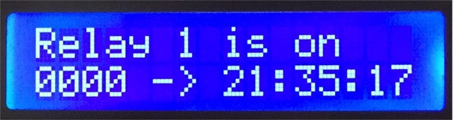
- statistics module has to know when particular relay goes on and off,
- pressing a button has to change display content and it also has to suspend services that would consume many CPU cycles, for example temperature reading from sensor,
- after some time temperature reading has to be renewed,
- and so on....
Every module is connected to Message Bus and can register for particular events, and can produce any events (first diagram).
On second diagram we can see event flow on pressing button.
Some components have some tasks than needs to be executed periodically. We could call their corresponding methods from main loop, since we have Message Bus it's only necessary to propagate right event (third diagram)
Step 6: Libs

Participated in the
Outside Contest 2017


