

Introduction: Three Trailers in One - Box, Car and Flat Top. the Box Top Trailer.


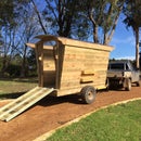


When building a new trailer, I wanted the most versatile trailer possible. It needed to be able to carry a large load of sand or mulch, be suitable for carrying pallets, able to be loaded by forklift and carry a ride on mower or small car. Box trailers in my area are the cheapest and most common trailer, but they are too restrictive for loading with a forklift and not wide enough for a car. Car trailers have nice low floor for loading but are very wide for towing and storage. Even with a design for removable sides, the wheels of a car trailer restrict loading with a forklift. The solution was a box top trailer.
The trailer needed small diameter wheels to keep the deck height as low as possible and I settled on a 4mx1.8m deck (approx 13'x6') which is big enough to carry most small to medium cars. After a search online failed to find suitable plans, I drew up my own plans for a box top trailer with tandem 13" light truck tyres, a 4m x 1.8m sheet steel deck and a 660mm (26") deck height. I also included a pivoting drawbar to assist in loading cars or unloading loose material.
The trailer was built and licensed in Australia where there are national standards for trailer licensing which sets out requirements including dimensions, axle layouts, braking and lighting. This design is based on these standards but check with your local licensing authority for licensing requirements. In Australia a trailer up to a maximum of 2000kg GVM (gross vehicle mass, trailer and load) with only one pair of brakes. This suited my needs and was the most economical approach so this design is for a 2000kg (4400lb) GVM trailer. With a tare (empty) weight of 500kg (1100lb), the trailer can carry a load of 1500kg (3300lb).
The trailer was built using springs, axles, U bolts, hubs, bearings, brakes and hitch supplied as a kit from a trailer parts store. It would be difficult to build a trailer that meets licensing requirements without buying these components from a reputable supplier as they need to be load rated to match the load ring of the trailer. Buying them as a kit is simple, ensures that they are all compatible parts and is probably the most economical way to source parts, particularly where delivery costs are concerned.
The total cost of the trailer including all new running gear, wheels and materials as well as licensing costs was $2900 Australian dollars. The major component of this was the running gear which was bought as a kit from a trailer parts supplier for approx $1000 although final costs including 5 new wheels and tyres and delivery was $1400. Other major costs were the steel framing, sheet steel deck and extruded aluminium sides. A detailed cost breakdown is included in step 5. Cost savings could be made with second hand wheels and tyres, but be aware that light truck tyres of the correct load rating to suit the trailer weight are required.
A welder and reasonable welding skills are required to build a trailer. If you are not confident with your welding, don't let this stop you attempting the project. Find somebody to assist you with critical structural connections such as the drawbar mount and knee joint and suspension mount attachment and the remainder of the project is a good project on which to develop your welding skills.
Step 1: Design
The design for the trailer uses square & rectangular hollow steel sections for the trailer structure and aims to keep the trailer simple to build. It uses small diameter wheels, 13" Light Truck wheels (dia 565mm) to allow the deck to be keep low (660mm / 26" deck height). It is designed for a tow ball height of approx 480mm (19") although this can be easily varied.
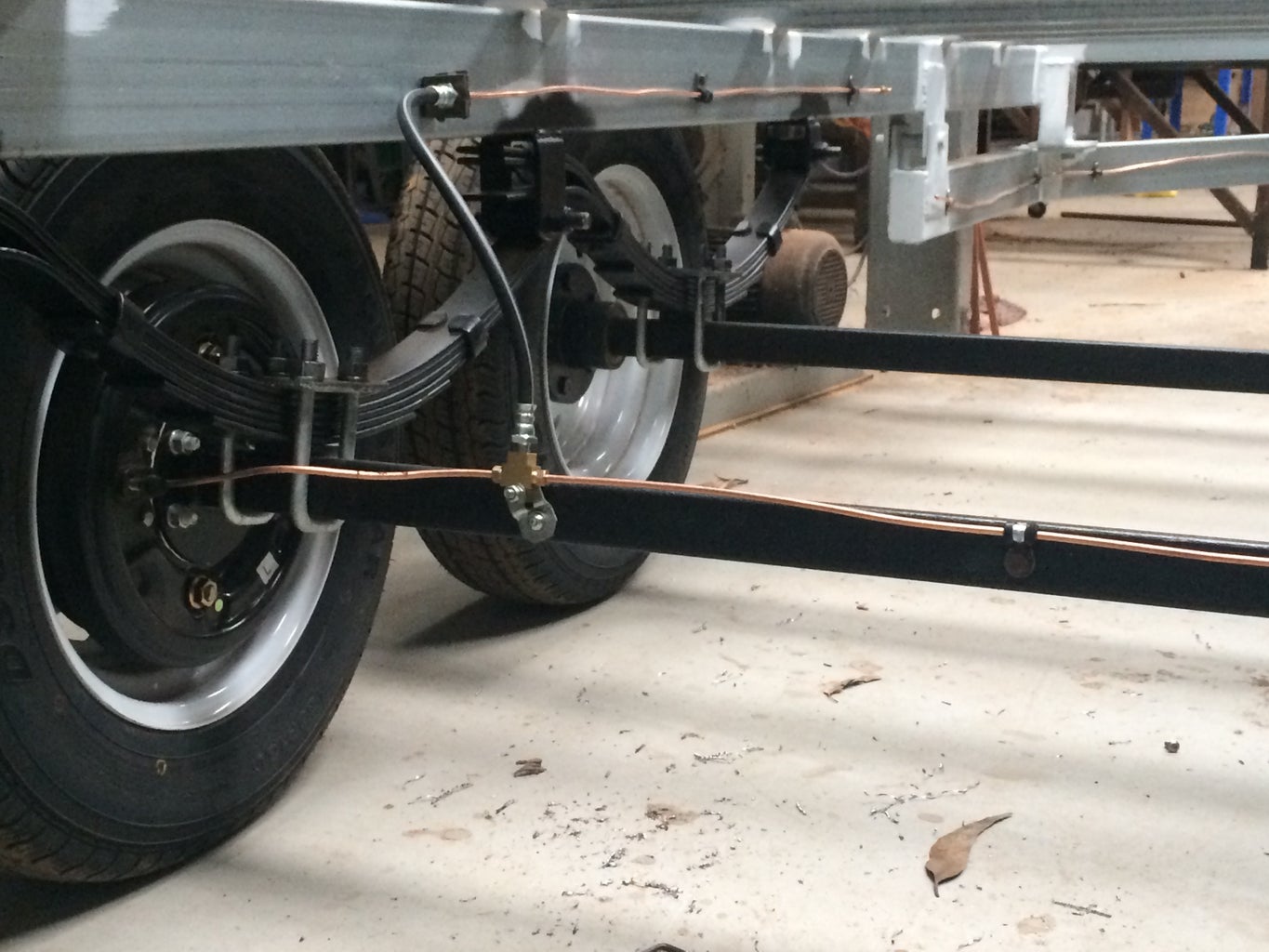
The trailer uses slipper springs and while these are not as good for sharing loads as the rocker type, they are robust, require less wheel travel, more economical, easy to install and have a lower mounting height suited to smaller wheels and a low floor height.
Minimising the deck height makes the trailer easier to load and unload and it makes it drive better on the road as reducing the load height also reduces the amount of roll.
While the deck height of the trailer is kept as low as possible, it is still a lot higher than a car trailer which has a car loaded between the wheels of the trailer, so to make it more practical to use this trailer as a car trailer, I have included a pivoting draw bar to to aid loading a car. The pivoting drawbar also can make it easier to unload a trailer load of mulch or sand. Two bolts securing the front of the drawbar are removed and a car jack is used to lift up the front of the trailer which tilts the trailer back on its rear wheels.
A PDF drawing of the trailer with key dimensions is included below. Send me a message if you want a CAD file.
Looking around the web for trailer designs I found that there were many websites offering designs for a fee but not so many free designs were out there. One web site that I would like to plug is Trailer Sauce from New Zealand. It has written instructions, great diagrams and excellent advice for building your own trailer however I think I've been able to come up with a simpler design to build.


Step 2: Materials and Equipment


Running Gear
Trailer running gear was sourced from a trailer parts supplier as a kit. There were a number of hub bolt patterns matching common vehicles to choose from and you need to specify the axle length required. You can also choose from cable, hydraulic or electric brakes. Electric brakes need a control fitted to the tow vehicle which can be inconvenient and I've had experience with hydraulic brakes in the past and found them ok so I used hydraulic brakes. The running gear for two trailers is shown in the first photo including springs, axles, brakes and hitches. The second photos also shows the tyres for two trailers with the components.
The kits we used were $1400 each including 5 new wheels and tyres and delivery across Australia and the kits came neatly packaged on a large pallet. They were sourced from Huntsman Products who have a fairly comprehensive online store and competitive prices but there are numerous suppliers of kits to choose from.
Running Gear List
2000kg rated ball coupling (tow hitch) with override brake operation and hydraulic cylinder
tow hitch bolts
2 x brake drums rated to suit trailer weight
hydraulic brake line (metal), splitter block, tube nuts, 3 flexible links (2 to allow for suspension movement between frame and wheels, one to allow for drawbar pivot movement.
2 x 40mm square axles, 60" long measured tip to tip. rated at 1100kg per axle.
4x leaf springs rated to min 560kg per axle. note the extra 10% allows for slipper springs not having a full load sharing of rocker spring setup.
mounting bolts and hangers. U bolts to mount axles on springs and hangers to mount springs on frame.
4x hubs and bearings. I used 5 stud Ford pattern. Other common sizes are available.
5x 13x5.5" wheels and 155/13 LT tyres to suit hub stud pattern. LT stands for light truck. Incl 1 spare. Note that the diameter of the wheel is important as a larger diameter wheel would require spacers to mount the suspension to maintain clearance to the underside of the deck.
Steel Frame and Deck
The framing for the trailer is all made from rectangular and square hollow steel tubing. The main chassis rails onto which the suspension is mounted is made from 100x50X3mm rectangular tubing. On top of the main chassis rails running across the trailer are cross members made from 50x50x2mm square tubing. Along the sides is an edge beam from 75x50x2.5mm rectangular tube. The steel comes in 8m lengths from the local steel supplier so the 4m deck was an ideal length, one length of steel making both beams.
As we were making two trailers, the photo above shows steel tubing cut for two trailers.
The steel used has a light galvanised finish that can still be welded but provides added corrosion protection without the need for galvanising the entire frame, significantly cheaper and avoids logistical challenges of transporting partly finished trailers to / from the galvaniser.
Misc plate required includes plate for capping RHS ends, mounting tow hitch (may come with hitch), drawbar pivot, mounting lights, mounting tie rail.
As well a structural members, a couple of lengths of ¾" or 20mm galvanised steel pipe was used for tie down rails.
Cutting List:
100x50x3 RHS 4000mm long x 2
75x50x2.5 RHS 4020mm long x 2, 45 degree mitred ends. Note cutting a mitre in the middle of an 8000mm long length of steel will give you two 4020mm lengths allowing a few mm for the saw cut. The reason this is a little longer than the main rails is so that the edge beams are slightly longer than the sheeting for the steel deck and can be set back from the edge of the beam to allow for the radii on the corners of the RHS.
75x50x2.5 RHS 1820mm long x 2, 45 degree mitred ends
75x50x2.5 RHS remainder of an 8m length after cutting the two 1820mm lengths above was used to make the drawbar.
50x50x2 RHS 1720mm long x 5
130x8mm plate x 8 drilled 1" pin (pin to be snug or tight fit) for draw bar pivot. This can be omitted if you don't want a pivoting draw bar and replaced with spacers to suit desired tower height.
Sheeting for deck, we used 1.6mm galvanised sheeting and sourced three 4m x 1.2m sheets, one sheet cut in half by the supplier on a large guillotine to deck out two trailers, i.e. 1 ½ sheets per trailer.
50mm thick spacer to sit on main chassis rail and give additional support under sheet steel deck, good idea if you are putting a car on the trailer. We used a treated pine sleeper ripped down to 50mm x 50mm
Lighting & Electrical
Lighting and reflectors were sourced online through ebay sellers which comprised
2 x LED rear combination lights (brake, tail, reflector and indicator)
1 x led number plate light
2 x LED white front position markers
4 x orange side reflectors
approx 6m 5 core trailer cable
trailer plug
Miscellaneous
2000kg load rated chain approx 500mm long
2000kg rated shackle
3x 4m long scaffolding planks. One is cut in half so two extra push in ends are required. Scaffolding planks are stronger and stiffer than typical ute side pressings.
hinges and catches available from a trailer or ute body supplier or make your own.
mudflaps (sheet steel or rubber) While it seems that mudflats would not be needed for this design which places the wheels under the tray, our local design rules required a mudflap that extends down to the centre of the rear tyre.
Paint - use etch primer over galvanising before painting with a finish coat
Step 3: Putting It Together


1. Weld 75 x 50 RHS frame for edge of deck. Frame is 4020mm x 1820mm. Take care to keep frame square and flat. This can be achieved by tacking joints in all corners before completing welds, working from a flat floor and welding opposing joints section by section rather than completing one joint before moving to the next.
2. Notch ends of 100x50 RHS beams 25mm deep so that edge frame sits in notches and top of edge frame sits 50mm above top of 100x50 RHS. This will allow the 50mm cross members to sit on the beam and sit flush with the top of the edge frame.
3. Sit edge frame on beams and then sit cross members in place. Clamp cross members flush with top of edge frame and check all dimensions for set out of the beams and cross members. Check that the trailer and the main beams are square and check that diagonals are the same length. I used a ratchet strap across the longer diagonal of the edge frame to pull it back into square. When satisfied that all members are in place and square, tack everything in position. Spacing of the main beams needs to match the centre to centre spacing of the springs. This dimension has some flexibility as the spring position on the axle can be adjusted with the U bolts when attaching the springs, however for maximum strength and maximum roll stiffness, keep the springs as wide as possible allowing at least 25mm clearance between the spring and the tyre. It is worth assembling the axles and wheels to check this dimension before welding the main beams in place.
Note on centre cross member: The centre cross member is not placed centrally to the edge frame, rather it is placed centrally to the axle group. This provides maximum clearance for suspension travel.
The centre of the axle group is typically placed between 50mm and 100mm behind the centre of the trailer. This is done so that with a central load there will be a small downward load on the towbar. For trailers that are more likely to carry even loads or rear biased loads, the distance of the axle group behind centre is largest. For trailers that will carry the load further forward or have front biased loading (e.g. front engine car) then the distance is kept to a minimum.
4. Check all the members are square a setout correctly before welding. Some people recommend not to weld across the flange of the main beams, just along the edge. This will still give enough strength and may reduce fatigue stress around welds across the flange of the beam. I don't think this is really essential, but if you do do this, I suggest filling the joints with a sealant before painting where there is no weld.
5. Turn frame over to assist in completing welds and while upside down fit suspension brackets. It is easier to weld brackets on when upside down. Weld suspension brackets to main beams. Note that centre bracket needs to be positioned so that the centre of the axle group is 50mm to 100mm behind the centre of the deck (see note above). Use the dimensions that I have provided on the drawing as a guide, but you will need to work out exact dimensions to suit the setout dimensions for your components as there are many different spring sizes available. Pay special attention to weld preparation when welding on suspension brackets, Remove galvanising and any rust with a grinder. After welding on brackets, inspect to ensure welds fully penetrate into both the main beam and the suspension hanger along the full length of the weld.
6. Press bushes into spring eyes and fit springs to brackets.
7. Turn over the assembly. It is getting heavy by now so you will need some assistance. Fitting the axles after the trailer is turned over may not seem as easy, but the axles are quite heavy so it will make it more difficult to turn over if you have the axles fitted. Prop the trailer up on the corners on saw horses or similar.
8. Fit brake drums, bearings and hubs to axles and attach wheels. Note that it may be a good idea to paint axles before fitting other components.
Roll axle and wheel assembly under the trailer, lower trailer frame onto axles and bolt axles onto leaf springs using U bolts. Note that at this point axles can be positioned roughly and bolts only partly tightened. We will come back later after drawbar is fitted and align the axles.
When you take the frame off the stands and sit the trailer on its wheels, the deck should be angled down a little toward the front of the trailer. This assists in ensuring a positive load on the tower of the tow vehicle when the trailer is empty. If the trailer sits the other way, there could be uplift on the tow bar and the trailer may feel more jiggly to tow.
9. Weld up 75x50 RHS drawbar. Check that drawbar width matches spacing between main beams. Cut pivot plates and drill a hole for a 1" pin. It will be easiest to drill the plates on a drill press before fitting to the drawbar.
Notes: This is a shorter than average draw bar, however it is sufficient to avoid striking the trailer with the tow vehicle with sharp reverse turns and aided by the length f the trailer, it tows well at speed.
10. Assemble pivot plates on 1" pin and clamp on two plates each side to draw bar. Set up a string line along the centre of the trailer deck extending past the drawbar. Align point of drawbar to string line and clamp remaining two plates each side to main beams. Check that drawbar can pivot without binding and tack plates to drawbar and trailer beams.
11. Remove pins and weld pivot plates to drawbar and main beams. Reassemble drawbar and fix pin in place. I used a short length of thick walled pipe welded to the end of the pin to fix pins.
12. Setup tow hitch mounting plate on drawbar and align with string to ensure the plate is central. Check bolts to mount hitch are clear of the drawbar member below and weld plate to drawbar.
13. Bolt on tow hitch and set hitch to required height. Measure and cut RHS front drawbar support and gusset plates. Drill plates and tack in place. Weld up front drawbar support plates. Note position drawbar support plates on drawbar to double as gusset plates to reinforce welded drawbar joint. Bolt in place with min 20mm high tensile bolts.
Step 4: Finishing Off

14. Align front axle by measuring diagonals from front edge of deck frame and centre front axle between sides. Check diagonal measurements from front axle to tow hitch are equal. Align rear axle parallel to front axle by measuring back from front axle. Tighten U bolts.
15. Fit hydraulic lines from master cylinder to brake drums with flexible couplings from the axle to the brake line on the frame. Support hydraulic lines on frame with saddles. Screw saddles to side of beams not flanges (top and bottom of beam) to avoid holes in flanges that can raise stress and cause cracking in flanges.
16. Weld on tie rails
17. Weld on plates to mount lights
18. Wire brush and prime all welded joints.
18. Tack on sheeting for deck then weld. Keep welds to min. size by keeping welder moving quickly to minimise any distortion as the deck requires a lot of welding.
19. Remove wheels and sit trailer on blocks ready to paint trailer. Minimum preparation should be to wire brush all welds and wipe down trailer with cleaner (e.g. methylated spirits) prior to painting. Ideally an etch primer should be used for all clean metal and galvanised surfaces prior to painting.
20. Run 5 core trailer cable from front drawbar to fight positions in RHS beams. Drill beam penetrations in webs (sides) of beams and fit grommets before running cables.
21. Fit lights, connect lights and plugs. Plugs and packaging typically shows wire colours, however there are plenty of diagrams on line if required so I won't go into details on wiring trailer lights.
22. fit mudflaps, check all bolts are tight.
23. Fill master cylinder with brake fluid and bleed brakes. Adjust brakes by tightening until there is drag on wheels then backing off adjuster nut until you can only just feel brake drag.
24. Cut scaffolding planks to length for trailer sides. Clamp in sides place. Position hinges and rivet hinges to trailer sides. Weld (or rivet or bolt) hinges to trailer frame. Note that it is reasonably easy to make your own hinges with some 3mm plate, pipe and rod that fits neatly in the pipe. Thick wall pipe is needed for ease of welding to assemble hinges.
25. Final paint touch up and test drive
26. Fit reflectors according to local licensing requirements.
Step 5: Costs
A summary of all trailer costs in Australian dollars is included in the table above.


