

Introduction: Toggle Switch Assistive Technology


This project was originally designed for V-LINC, a non-profit of volunteers that specialize in Medical engineering solutions. As a new volunteer, I was assigned to solve the problem. A client who held a position as an telephone operator was sometimes dropping calls that needed to be transferred. The problem was analysed and the discovery was that the client did not have the dexterity to hold the off-hook button down long enough to guarantee transfer.
The solution I came up with involved designing a small 3d printed box that snapped on top of the off-hook button. Inside the box was a large toggle mechanism that snapped in to position by pushing or swiping across the toggle part. The bottom of one side extended enough to push the off-hook button down to engage the switch. The operator can now transfer calls with out trying to hold the button down long enough to transfer a call. Dropped calls became a thing of the past and the special needs client is now successfully performing his duties.
This INSTRUCTABLE is not just intended to show the solution but to show how this simple concept can be used to convert any push button into a toggle switch of any size. Projects for children, handy-caped, elderly, or any application that might benefit from having a larger or easier means of controlling a switch.
TOOLS
3d printer
any CAD or modelling software( I used Blender )
wrench set
small metal cutter for brass rod
Parts
One mountable magnet ( Neodymium magnet worked well )
Two flat Hex head screws ( any screws that have or can be filed to a flat surface and sticks to the magnet well.)
toggle part ( 3d printed )
base box (3d printed box) or other surface
Mount for desired surface (base box served as mount for toggle )
rod long enough to go through toggle and box ( I used 3mm brass rod )
Step 1: Measurements

For the telephone I measured the inside of the frame around the off-hook button, the depth and the location of the switch. For a different kind of project you mjght need to measure the position of the button switch you want to control, than transfer the co-ordinates to the top plate. You would also need the depth from the top to the button when pressed.
Step 2: Basic Principle

Using a magnet instead of springs has real advantages. It reduces the wear factor and maintenance requirements. It also simplifies the design.
The idea is to align the screws (shown as white dots in the picture above) so that they touch the magnet when toggled forward. They don't have to touch at exactly the same spot but must touch on the magnets strong surface. If the magnet has a hole in the middle be careful not to line up over the hole. The magnet is weaker even with a screw in the hole (metal screw not ideal) .
The two screws in the toggle part should be made of a metal strong enough to feel the pull and snap and hold when tested. I used a N52 Neodymium bar magnet I had from another project. I aligned both screws to barely touch one side away from the screw in the center of the magnet.
Below is a video of the model alignment. Just make sure each screw face is vertical when the toggle part is in the locked position.

Step 3: Toggle Bar

You are going to need a metal rod to go through the toggle part for strength. I use a 3 mm brass the length of the box. You could use anything strong even a nail. Just make the holes large enough to accommodate it. I threaded the ends in the prototype but found it wasn't necessary in the finale unit. If your holes are lose just heat up the PLA and it will expand to make a tight fit. The rod does not turn so there is not much stress on it. You can add some glue or cover the ends if needed for your application.
Step 4: It Works
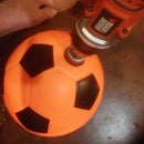
The toggle switch I made was large enough that one could just swipe it with any part of a hand to flip it in the other position.
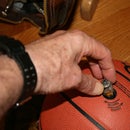
Step 5: Assistive Pointer

In case you are interested the Tee used is a common device for assisting one who has a closed fist or similar constraint. I made this one by taking a 4" section of 1" PVC and filling it with scrap PLA; just heat and push into the PVC. Make sure you fill the middle section solid, so the worm screws can set. I put two holes one on each side and two worm screws, than I heated the worm screws with a heat gun and screwed then in. It made a tight fit. You could probably just use one screw or none if you didn't plan to change the pencil out. A regular flat head screw would also probably work; just counter sync to fit flat.
I found that different length pencils are needed for different applications. If you need a bigger tip you can add a pencil top eraser over the pencil.
I am entering this Instructable in the 3d print contest. If I win the Ultimaker I plan to use it to design assistive technology products. Wish me luck.

Participated in the
Beyond the Comfort Zone Contest

Participated in the
3D Printing Contest 2016


