

Introduction: Toggle Switch and Button Logic


This instructable covers flip switch and push button logic. I cover how to read a switch's status and use it to control processes or call a function. The sample program in this instructable, has functions that are straight forward to copy, paste, edit, and use in your own projects.
The program logic covers the following use cases:
- Use a switch to call a function when a button is pressed, or a toggle is flipped. For example, an LED light stays on while the button is held down. The light is off when the button is released, or not pressed.
- When a button is pressed, or a toggle is flipped, turn a device on by calling a function. When the button is pressed a second time, the device is toggled off. For example, when a button is pressed and released, an LED light is turned on and stays on. When the button is pressed and released a second time, the LED light turns off and stays off. The logic allows you to toggle a device on and off.
Call a function when a button, or toggle, is pressed; or call the function when the button is released. This gives you the option of when to call your function: at time of press, or at time of release.
Without program logic, when a button is pressed, if a function is called, and the function maybe called over and over while the button is held down; even though you only want it called once, regardless of how long you hold the button down. Or, you may want the function to be called when releasing the button, rather then when the button is pressed and held down.
I also cover wiring options:
- Use a pull down resister,
- Or, in the program, change the pin mode setting and the Arduino will use an internal resister, which saves you wiring a extra resister into the circuit.
I'll cover the following switch toggles and buttons:
- A button, that when pressed allows current to flow. When released, it goes back to the no-flows state.
- A flip switch toggle, that when flipped and held, allows current to flow. When released, it goes back to the no-flow state. A flip switch toggle works fundamentally the same as a button. The flip switch toggle I use, can be flipped in 2 directions, to allow 2 circuit flows. It's called an on/off/on SPDT 3 position momentary toggle.
The steps in this instructable, is to wire and test an Arduino board. The next step is wiring a flip toggle switch, 2 buttons, and 2 LED lights. Once wired, load and run the sample program that reads the switch statuses and call functions based on the statuses.
This instructable requires that you have the Arduino IDE installed. You are also required to have the basic skills to download an Arduino sketch program from the links in this project, create a directory for the program (directory name, same as the program name). Once downloaded, the next steps are to load the program into the IDE, view it, and edit it. Then, upload the program through a USB cable to your Arduino board.
Supplies
- Arduino ATmega2560 (Mega), Uno, or Nano ATmega328P microcontroller board with a USB cable to connect to your computer.
- 2 breadboard buttons
- 1 SPDT On/Off/On 3 position momentary toggle.
- 2 LED lights
- 2 10K resisters
- 1 1K to 5K resister
- Breadboard
- Breadboard wires or wire cables (male to female)
I bought the parts on eBay, mostly from Hong Kong or China distributors.US distributors may have the same or similar parts for reasonable prices and faster delivery. The China parts take from 3 to 6 weeks to be delivered. The distributors I've used have all been reliable.
Approximate costs: $15 for a Mega, $3 for a Nano. My SPDT On/Off/On 3 Position Momentary toggle, is a 6mm (0.2inch) diameter micro mini. I bought 10 toggles for $6.79.
Step 1: Test Your Arduino Nano, Uno, or Mega

If you are using an Arduino Nano, plug it into the Breadboard. Connect power and ground from the Arduino to the breadboard's power bar. Connect the Arduino 5V+ pin to the breadboard's positive bar. Connect the Arduino GND (ground) pin to the breadboard's negative (ground) bar. The power bar will be used to connect to the buttons and toggle switch.
Download and run the basic Arduino test program: arduinoTest.ino. While running the program, the onboard LED light will turn on for 1 second, turn off for 1 second, and continuously cycle. Also, messages are posted which can be viewed in the Arduino IDE Tools/Serial Monitor.
+++ Setup.
+ Initialized the on board LED digital pin for output. LED is off.
++ Go to loop.
+ Loop counter = 1
+ Loop counter = 2
+ Loop counter = 3
...
Note, you can use this program to test your Nano, Mega, or Uno, they all have the same pin number for the onboard LED light.
Step 2: Connect the Switches and Buttons
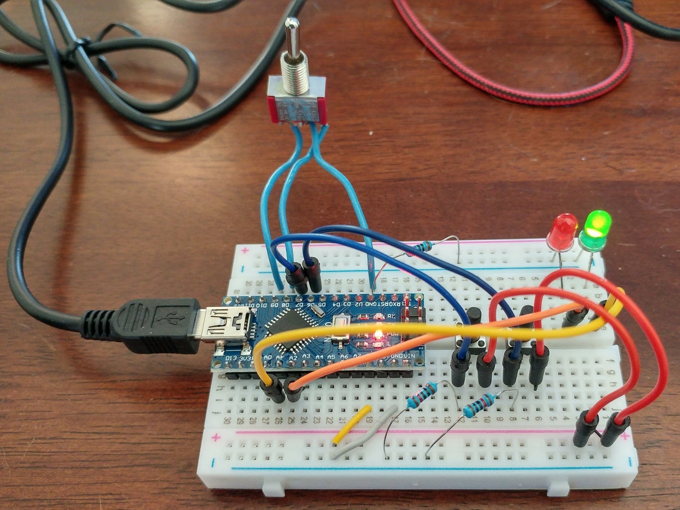

My breadboard circuit has the following components and connections.
2 buttons have a pull down resister.
- One side of each button is connected to a Nano digital pin (pins 6 and 7), and a 10K resister is also connected to the button on the Nano digital pin side.
- The other side of the resister connects to ground; hence the name, pull down, pulled down the Nano digital pin to ground.
- The other side of the button is connected to 5V+.
When the button is pressed, current flows from 5V+ through the button, through the resister to ground. The digital will change from LOW(ground) to HIGH(positive voltage).1 on/off/on toggle switch.
Each side of the toggle are pull up circuits, no resister required.
- The middle contact of the toggle, is connected ground.
- The other 2 contacts are connected to Nano digital pins 8 and 9.
- I had soldered 3 inch wires to each toggle contact, to connect to make it possible to connect the toggle contacts to the breadboard.
2 LED lights.
- The positive side of the LED is connected directly to a Nano digital pin (pins A1 and A2 which are analog pins used as digital pins).
- The other side of the LED lights are connected through a 5K resister to ground. I used a 5K resister because it works and I have a number of them.
Following, the connections are listed again, with the corresponding program pinMode statement, and circuit flow information.
For the breadboard push buttons,
Pull down circuit connections,<br>    Arduino digital pin to one side of the switch or button.
    Ground to 10K ohm resister, to the same side of the switch.
    5V+ to the other side of the switch.
  Use,
    pinMode(inPinDown, INPUT); // requires a 10K pull-down resistor.
  Arduino digital pin reads LOW.
    When the switch is closed (button pushed), the digital pin reads HIGH.
For the on/off/on SPDT toggle,
Pull up circuit connections,
    Arduino digital pin to one side of the switch or button.<br>    Ground to other side of the switch or button.
  Use,
    pinMode(inPinUp, INPUT_PULLUP); // Which doesn't require any resister.
  Arduino reads HIGH from the digital pin.
    When the switch is closed (button pushed), the Arduino reads LOW
For the LED lights,
For toggle testing, connect 2 LED lights to Arduino digital pins.
    Arduino digital pin to the positive(+) side of the LED light.<br>    1K resister to the ground(-) side of the LED light. Can use various sizes of resisters: 1K to 5K.
    Other side of the resister to ground
Step 3: Test the Switch and Toggle Logic
Download and run the logic test program: switchInputTest.ino, on your Arduino. This program was tested successfully with a Mega and a Nano. The program checks switch states. If the state changes, an LED will turn on or off, based on the program logic.
Program Notes
In the setup section, set the pin modes (pinMode):
- OUTPUT for the LED lights
- INPUT for the pull down resister switches.
- INPUT_PULLUP for the pull up switches that use a resister that's built into the Arduino.
void setup() {
  ...
  pinMode(LED_PIN, OUTPUT);               // Onboard LED light
  pinMode(LED_TOGGLE_PIN1, OUTPUT);
  pinMode(LED_TOGGLE_PIN2, OUTPUT);
  Serial.println("+ LED output pins initialized.");
  // Initialize the button pin.
  pinMode(PIN_PULL_DOWN1, INPUT);         // Requires a 10K resister.
  pinMode(PIN_PULL_DOWN2, INPUT);         // Requires a 10K resister.
  pinMode(PIN_PULL_UP1, INPUT_PULLUP);    // Doesn't require a resister.
  pinMode(PIN_PULL_UP2, INPUT_PULLUP);    // Doesn't require a resister.
  Serial.println("+ Input pins initialized.");
  ...
}
When the program starts, the onboard LED light and the 2 LED lights are off. In the IDE monitor window, the Setup messages are displayed.
+++ Setup.
+ LED output pins initialized.
+ Input pins initialized.
+++ Go to loop and check if the switches are switched.
In the program loop, the delay statement is used to control what is called debounce. When contacts are made, in a very short interval of time there can be a connect, disconnect, connect, disconnect, until the connection becomes stable. The delay statement will take care of that occurrence in that the connection is seen as connecting only once.
void loop() {
  checkPullUpSwitch();
  checkPullUpToggle();
  checkPullDownSwitch();
  checkPullDownToggle();
  delay (100);
}
Switch Logic
Push one of the buttons. While the button is held down, the onboard LED light remains on. When released, the light goes off. The button's function name is, checkPullDownSwitch().
Flip the toggle in one direction, and while it is held in that direction, the onboard LED light remains on. When released, the light goes off. The toggle's function name is, checkPullUpSwitch().
The program structure is the same for both functions, checkPullDownSwitch() and checkPullUpSwitch(). The circuit shows that the same basic function works with multiple types of switches.
Note, the end result is that LED lights turn on and off the same way, whether using a pull down resister or not.
// Turn light on when the button is pressed.
boolean setPullDownState1 = false;
void checkPullDownSwitch() {
  // When using a pull down resister, LOW is not switched, HIGH is switched.
  if (digitalRead(PIN_PULL_DOWN1) == HIGH) {
    if (!setPullDownState1) {
      Serial.println("+ Pushed, pull down pin switch 1, LED on.");
      setPullDownState1 = false;
      // Logic: button pushed down.
      digitalWrite(LED_PIN, HIGH);
    }
    setPullDownState1 = true;
  } else {
    if (setPullDownState1) {
      Serial.println("+ Released, pull down pin switch 1, LED off.");
      setPullDownState1 = false;
      // Logic: button released.
      digitalWrite(LED_PIN, LOW);
    }
  }
}
Toggle Logic
Push the other button down and release it, and one of the LED lights will turn on and remains on. Push the button down again, and release it, and the light goes off and stays off. The button's function name is, checkPullDownToggle().
Flip the toggle in the other direction and release it, and one of the LED lights will turn on and remains on. Flip the toggle in the same direction a second time, and release it, and the light goes off and stays off. The toggle's function name is, checkPullUpToggle().
The program structure is the same for both functions, checkPullDownToggle() and checkPullUpToggle(). Again, the circuit shows that the same basic function works with multiple types of switches. The additional logic shows how to use the switches to toggle a device using a Boolean value. In the sample program, the values are: theTogglePullDown and theTogglePullUp.
Note, the end result is that LED lights turn on and off the same way, whether using a pull down resister or not.
// Toggle light on and off each time the switch is flipped.
boolean theTogglePullUp = false;
boolean setPullUpState2 = false;  // Case the button is pressed and held, only toggle once.
void checkPullUpToggle() {
  // If the button is pressed (circuit closed), the button status is HIGH.
  if (digitalRead(PIN_PULL_UP2) == LOW) {
    if (setPullUpState2) {
      if (theTogglePullUp) {
        Serial.println("+ Flipped, pull up pin switch 2, toggle off.");
        theTogglePullUp = false;
        // Logic: switch flipped, circuit closed.
        digitalWrite(LED_TOGGLE_PIN1, LOW);
      } else {
        Serial.println("+ Released, pull up pin switch 2, toggle on.");
        theTogglePullUp = true;
        // Logic: switch released.
        digitalWrite(LED_TOGGLE_PIN1, HIGH);
      }
    }
    setPullUpState2 = false;
  } else {
    setPullUpState2 = true;
  }
}
Step 4: Summary

In the above photo, you can see that my Altair 8800 emulator has a lot of toggle switches. The logic functions for this instructable application, came from that project. Since each switch has it's own logic function, it makes it easy to add switch logic functions into other projects.
Cheers,
Stacy David


