

Introduction: Touchscreen Controlled Marionette


We are going to have a little fun with the Intel® Galileo development board. This time around, we’ll make a simple puppet control system. We’ve put together a “running robot” marionette with a simple mechanism that uses a continuous servo. We’ll be use a touchscreen interface to control various outputs using sliders and switches.
As always, you can modify the designs to suit your needs. We will teach you how to incorporate touchscreens, and make the interface necessary for controlling the Intel® Galileo Gen 2 board.
So, let’s start the puppet show!
Here is a video of the completed project.
This tutorial was originally published on Intel Communities here.
Step 1: Needed Components


- Intel Galileo Gen 2
- Arduino Protoshield
- Galileo power supply
- Adafruit TFT touch screen
- LED
- 300 Ohm resistor
- Continuous servo motor
- Colored single core wires
Step 2: Needed Tools


- Enamel wire (0.2 mm thick)
- 4 mm MDF components - lasercut according to drawing
- 6 mm MDF components - lasercut according to drawing
- Plexiglas components - lasercut according to drawing
- Eyehooks used in sewing (can be substituted with bent wire if needed)
- Fluted pins used in woodwork (6 mm x 30 mm)
- Fishing line
- Stiff wire
- Wood glue
- Hot glue sticks
- Magnets
- Business card (or any stiff paper – used as a spacer)
- Nuts and bolts
- Lasercutter
- Mallet/Hammer
- Screwdriver
- Soldering iron
- Hot glue gun
- Needlenose pliers
- Scissors
- Wirecutters
Attachments

Step 3: Sort the Lasercut Pieces for Easier Construction

Sort all the pieces according to the image
Step 4: Make Rotation Joint

- Glue together 2 Part J rings
- Hammer a fluted dowel into the hole until one side is flush
- Make 4 units
Step 5: Assemble Lower Leg


- Glue Part H4, H5, and H6 together
- Insert an eyehook into the gap
- Glue Part H3, H2, and H1 to the assembly
- Make the left and right lower leg (they are identical)
Step 6: Assemble Upper Leg


- Cut small rectangles from a business card to be used as a spacer
- Glue a paper spacer between Part G1 and G2
- Glue Part G3 to the assembly
- Insert a rotation joint (like before)
- Glue Part G4 and G5 to the assembly
- Glue a paper spacer to the assembly
- Hammer a fluted dowel into the hole until one side is flush
Step 7: Attach the Lower Leg Assembly


- Glue and gently hammer Part G6 to assembly to complete the leg. The larger hole should be over the rotation joint so that it moves freely.
- Make the opposite leg (they are NOT identical, but rather a reflected assembly).
Step 8: Assemble Lower Arm


- It is very important that Part B1 and B6 are placed correctly so thatthe joint is able to move correctly. Though not shown in this instruction, it is suggested that you wait until after previous steps to glue these pieces on.
- Glue Part B1, B2, and B3 together
- Insert an eyehook into the gap
- Glue Part B4, B5, and B6 to the assembly
- Make the left and right lower arm (they are identical)
Note: The arm on the right side of the image is INCORRECT. As stated earlier, if the parts are glued this way, the rotation of the arm is limited and will not work properly. We fixed this later in the instruction.
Step 9: Assemble Upper Arm


- Glue a paper spacer between part A6 and A5
- Glue Part A4 to the assembly
- Insert a rotation joint (like before)
- Glue part A3 and A2 to the assembly
- Hammer a fluted dowel into the hole until one side is flush
- Glue a paper spacer to the assembly
Step 10: Attach the Lower Arm Assembly

Note: It is important to check the rotation of the arm at this point. It should move similar to your own arm.
At this point, if you have not glued on Part B1 and B6, do so now. Look final image in this step to ensure this is done correctly.
- Glue and gently hammer Part A1 to assembly to complete the arm. The larger hole should be over the rotation joint so that it moves freely
- Make the opposite arm (they are NOT identical, but rather a reflected assembly)
Note: In this picture, the arm on the right side of the image is incorrect. The eyehook should be placed on the other side. We corrected this in later images.
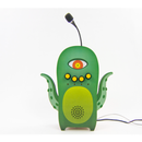
Step 11: Assemble Head


- Glue Part I4 and I5 together
- Glue on Plexiglass eye covers
- Glue Part I3, I2, and I1 to the assembly
- Insert fluted dowel into base of the head
Note: If you want to include an LED in the head, do not glue on Part I1 until you have installed one.
Step 12: Assemble Chest Frame


- Slot together Part K2, K5, K6, and K9. (Note the orientation of Part K5 and K6)
- Insert Part K10 and K11
- Slide on Part K12
- Place Part K1, K4 and K7. (Note the orientation of the parts)
Step 13: Place the Plexiglas Heart Cover


Hot glue Part K8 onto the assembly
Step 14: Assemble the Body Parts

Gently the arms, legs, and head onto the chest frame
Step 15: Assemble the Electronics Housing


- Insert nuts into the slots provided in Part L4, L5, L6, and L7
- Slot Part L4, L5, and L6 into L3 and secure with bolts
Step 16: Assemble the Stand Supports

- Bolt together Part L1 and L8
- Bolt together Part L2 and L9
- Attach those supports to the electronics housing
- Attach Part L7 between the supports
Step 17: Assemble the Turning Mechanism


- Glue together Part M1 and M2 to make a large wheel
- Hammer a fluted dowel into one hole
- Hammer another fluted dowel into center hole on electronics housing
- Attach the continuous servo motor from the back. (Note: Do not insert it through the hole, as this will place the wheel too far from the face of the housing)
- Insert the turning arm into the large wheel
- Attach the large wheel to the continuous servo motor
- Hammer a fluted dowel into one hole of Part M3
- Push down 2 Part J (rings) onto the dowel on the electronics housing
- Place on Part M3 and secure with Part J (ring)
- Push down Part J (ring) onto the dowel on the large wheel
- Use Part M4 to connect Part M3 dowel and the large wheel dowel and secure with Part J (ring)
Step 18: Secure Marionette to Electronics Housing

- Cut two long pieces of stiff wire and weave them through the three holes on the back of the marionette
- Slide the wires through Part K3 and secure the wires to the bottom of the electronics housing
- Adjust the wires until the marionette is positioned under the turning mechanism
Note: At this time, you can attach magnets to the back panel to make it easily removable. The same can be done with the head if not already glued into place.
Step 19: Attach the Marionette to the Turning Mechanism

- Turn the large wheel until the armature reaches the highest point
- Raise the arm opposite it and secure it with fishing line to the armature
- Raise the leg on the same side as the raised armature and secure with fishing line
- Turn the large wheel until the armature reaches the highest point on the other side
- Repeat steps for the remaining limbs
Step 20: Solder the Electronics

Use the schematic to solder the electronic components together
Step 21: Attaching the Electronics to the Electronics Housing

- Place the Galileo Gen 2 in the housing
- Attach the Protoshield
- Attach the touchscreen
- Attach the motor
- Insert the LED into the back of the marionette
Whew! We’re done with that part! Now lets move on to the preparing the electronics.
Step 22: Download the Sketch and Libraries
Look for TouchScreenMarionette from the attachment and place it in the sketchbook folder
Download the libraries. There’re 3 libraries used in this example:
- Adafruit GFX
- Adafruit ILI9341
- Adafruit TouchScreen
You can find the libraries in the attachment. The ILI9341 library and Adafruit TouchScreen library are specially modified to fit for Intel Galileo.
Attachments
Step 23: Install the Libraries
Place the library folders under hardware/x86/libraries/ in your Intel Arduino IDE installation. They can be as well put under sketchbook folder/libraries, but the libraries specifically made for Galileo may confuse regular Arduino installations.
Step 24: How to Run the Robot
- Plug in the power supply
- Wait until it says “Calibrating...” on the TFT screen
- Perform the calibration as directed on the screen by pressing the white rectangle on the corners. (See video)
- The interface will appear once calibration is complete. There are three different components:
- a slider
- a button
- a checkbox
The Slider is for adjusting the servo speed (equivalent to 0 to 180 as servo.write())
The button is for turning on/off the servo
The checkbox is for turning on/off the LED inside the robot
Step 25: The User Interface
A simple UI library is built to work with the touch screen. Library files can be found under in the sketch folder, util.h and util.cpp. Looking into the library files will give you an idea about how to customize the components or how to make your own components.
The size of all three components - slider, button and checkbox - can be configured. The initialization function, begin(), accepts four parameters: x, y, width, height. The width and height parameter has default values, which you can override by passing different values.


