

Introduction: Tracked Arduino Robot

This Instructable will show you how to build a tracked Arduino-controlled robot.
The content is organized as follows:
- Sourcing Parts: All of the necessary parts have been compiled, as well as resources to review their specifications and links to where the parts can be purchased. We compile parts starting with:
- Chassis
- Gearbox
- Arduino Uno
- Motor Shield
- Ultrasonic Distance Sensor
- Micro Servo
- Motors
- Batteries
- What tools will I need? A complete list of tools that will be useful for the construction of the robot.
- Assembly of the Chassis: The chassis kit comes with paper instructions that are quite good. The pictures are designed to be supplemental to the paper instructions.
- Assembly of the Gearbox: Same method as above, pictures attached to make assembly easier.
- Build a Battery Support Box
- Mounting the Gearbox
- Tidy Up the Motor Wiring
- Attach the Arduino to the Chassis
- Slide the Motor Shield into the Arduino
- Mount the Ultrasonic Sensor
- Wire Up the Ultrasonic Sensor
- Mount the Battery
- Load Your Program
- Finished Robot!
Step 1: Sourcing Parts: Chassis

The mechanical parts make up the body of the robot. This includes tracks, wheels, axles, and the wooden base to mount everything to.
About the Chassis Kit:
For this project, the Tamiya 70108 kit was used. It is cheap, easy to assemble, and a perfect base for a robot because it has tank steering, in other words, the robot can turn completely around in its own length. The basic kit comes with one motor and can go forward and backward, but cannot turn. This is not very useful to us, so the solution is the Tamiya 70168 double gearbox kit.
Research the Tamiya 70108 Tracked Vehicle Chassis Kit
Buy the Tamiya 70108 Tracked Vehicle Chassis Kit from Amazon
Picture courtesy of Tamiya
Step 2: Sourcing Parts: Gearbox

About the Double Gearbox:
The 70168 Gearbox is easy to assemble and enables our robot to make turns. It does this because each track is powered by a separate motor. The kit also has four gear ratios to choose from, so if the robot needs more speed or more torque, the gearing can be changed to compensate.
Research the Tamiya 70168 Double Gearbox
Buy the Tamiya 70168 Double Gearbox from Amazon
Picture courtesy of Tamiya
Step 3: Sourcing Parts: Arduino Uno

The robot needs something to tell the motors when to turn, how fast, and for how long. The robot also needs a way of deciding if it needs to turn left or right, stop, and how to interpret signals from its sensors. In short, the robot needs a brain.
The brain of the robot is the Arduino Uno. Based on inputs from sensors, the Arduino acts on logic that is written by the programmer, and creates outputs.
Research the Arduino Uno Rev 3
Buy the Arduino Uno Rev3 from Amazon
Step 4: Sourcing Parts: Motor Shield

An Arduino Shield is a component that can be placed over the Arduino and all the pins of the shield line up with the receptacles in the Arduino. This arrangement makes it very easy to have multiple components without worrying about the logistics of the wiring. This is where the robot pictured will differ from the robot that will be produced from this Instructable. The pictured robot uses a different version of the Seeedstudio Motor Shield, a version 1.2 instead of version 2.0. The 2.0 version is an improvement as it doesn't use the proprietary Grove style connectors, and it is now possible to use jumpers instead, which are cheaper.
Research the Seeedstudio Motor Shield 2.0
Step 5: Sourcing Parts: Ultrasonic Sensor

The HC-SR04 Ultrasonic Distance Sensor is the eye of the robot. With the HC-SR04 it is possible for the robot to gather real world information to feed to the Arduino brain. To be more accurate, the HC-SR04 uses sonar more like a bat, sending out sound waves and measuring the time it takes for them to return. By using the speed of sound, it is possible to calculate the distance between the sensor and the object being detected.
Research the HC-SR04 Ultrasonic Distance Sensor
Step 6: Sourcing Parts: Micro Servo

*Optional - This part would be placed between the ultrasonic distance sensor and its mount.
The SG90 micro servo is used on our robot like a human neck. It allows the ultrasonic sensor to turn in different directions, which is much better than having a fixed position on the robot.
Alternatively, it is possible to set up an array of multiple ultrasonic sensors, much like a fly's eye, with each sensor measuring distance from a different angle.
Research the Tower Pro SG90 9g Micro Servo
Step 7: Sourcing Parts: Motors

The basic chassis kit comes with 130 size motors, but they are 3 volt motors that pull too much current when stalled. Replacing them with Pololu #1117 motors of a higher voltage means that less current will be pulled through the drivers when stalled. This keeps the motor drivers from burning out.
Research and Buy the Pololu 130 Size 6v Motors from Pololu x2
Step 8: Sourcing Parts: Battery


A great way to power the robot is by using a high technology Lithium polymer battery. These batteries will power your robot for hours. Judge the capacity by the mah (milli-ampere-hour) rating, a higher number means higher capacity.
Be aware when using a Lithium Polymer battery that a smart charger is recommended, which drives the price up quite a bit.
For a cheaper alternative, you could use four AA batteries in series and a holder.
Research and Buy the Turnigy 1.8 (1800mah) nano-tech LiPo Battery from HobbyKing 7.4 Volts
or
Buy a four AA battery holder from Amazon, do not forget the AA batteries!
Step 9: Getting Ready for Assembly: Tools


A number of tools are necessary for the construction of the robot. This are listed below.
- Screwdriver set - Syba toolkit from Amazon
- Soldering Iron (optional) - Simple soldering iron from Harbor Freight
- Hobby Knife - Xacto hobby knife from Amazon
- Wire Strippers - Wire strippers from Harbor Freight
Step 10: Start Assembly: Chassis


Follow the instructions included in the chassis box. When the parts are freed from their plastic, they should look like the first picture.
- Parts inventory
- Mark Arduino mounting holes.
- Drill Arduino mounting holes. Along the sides, make notches with the hobby knife for the gearbox mount.
- Attach idler axle mounts.
- Attach bogey axle mounts.
- Detail of axle with idler wheels on it.
- Mount idler axle, wheels, and wheel securing caps.
- Attach bogies and wheel securing caps.
- Flip chassis upright.
Step 11: Start Assembly: the Gearbox


Follow the instructions provided in the box. The gearbox looks intimidating, and the small parts are hard to hold, but it is not as complicated as it looks. Be sure to slick the gears with the grease provided to reduce friction.
Refer to the pictures for step by step supplementary instructions to the paper instructions included in the kit.
Step 12: Build a Battery Support Box


This battery box was built using a Meccano Erector set. Erector sets are great sources for frames for projects. The battery box does not need to be high tech, the iteration before this robot was made from cardboard.
Step 13: Mount the Gearbox to the Chassis


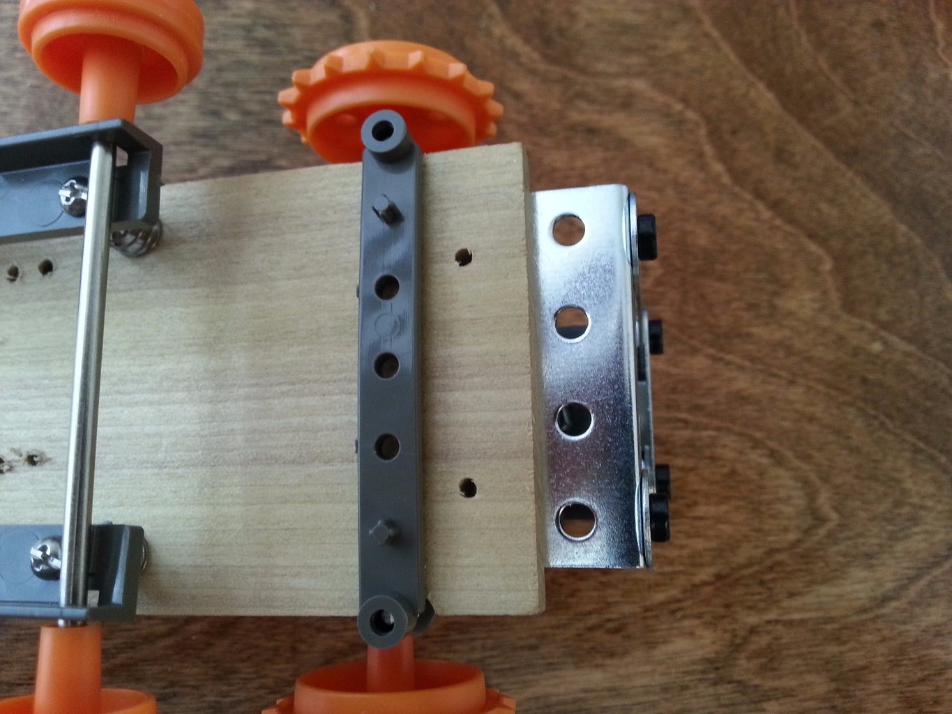

The gearbox is slightly too wide for the chassis, so the bolts go down through the gearbox through the notches and into a sandwich plate. The sandwich plate also pinches the battery holder down, which slips underneath the gearbox.
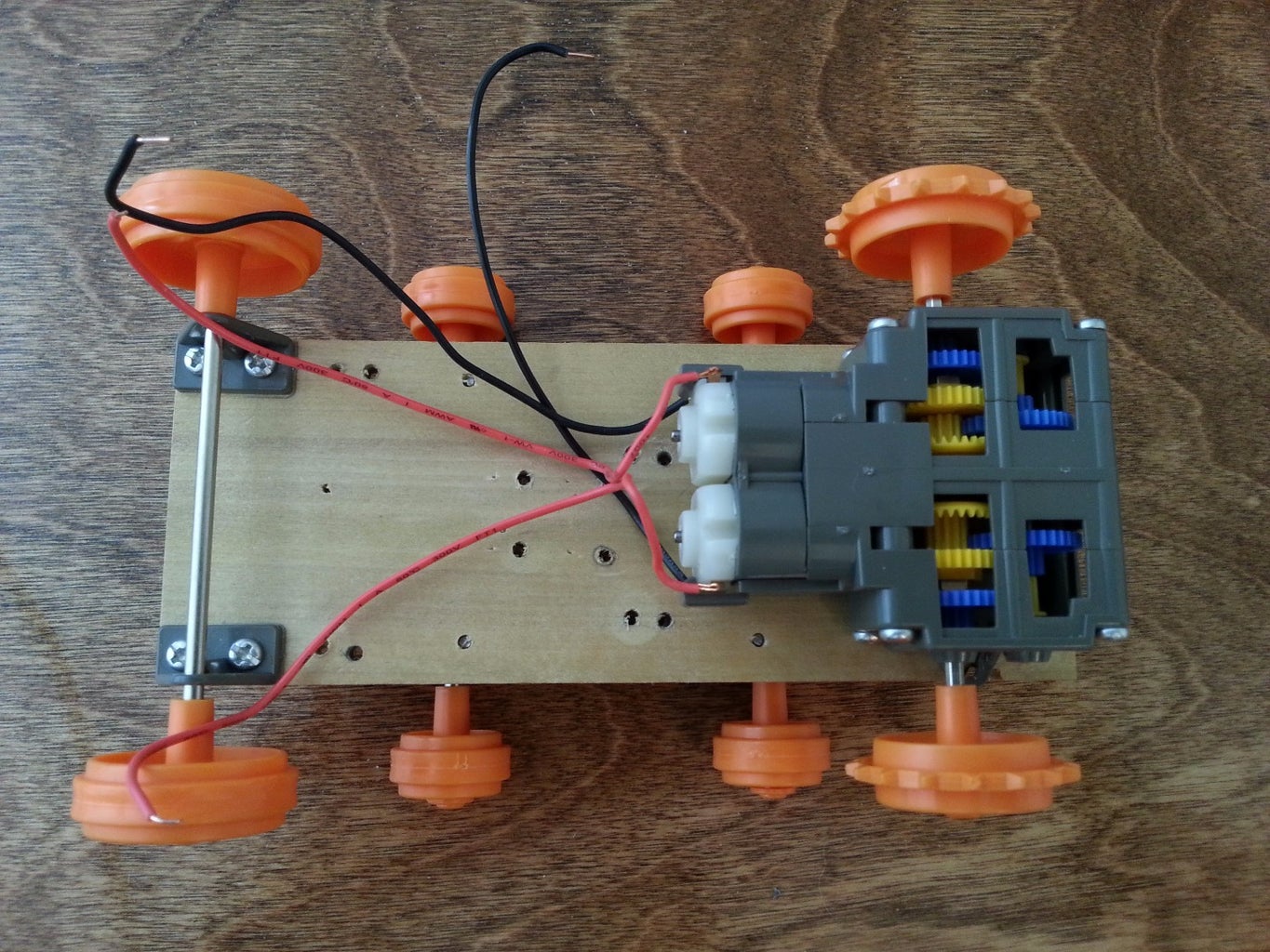
Step 14: Tidy Up the Motor Wiring
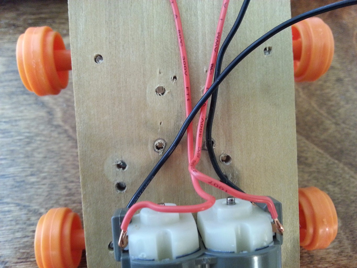
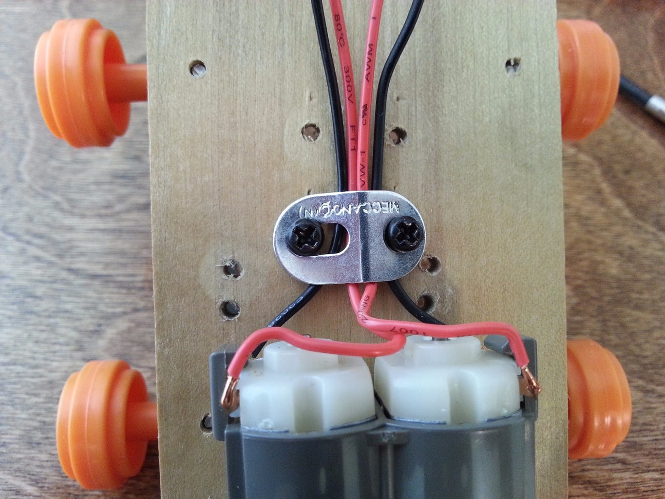
For this step, a two-hole erector strut slightly flattened pinches the wires to provide strain-relief. Organize your wires so that they are easy to tell apart after you cover them with the Arduino.
Step 15: Attach the Arduino to the Chassis

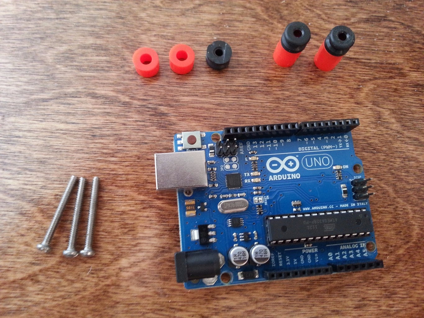


Using the drilled holes from the very beginning of the project, use standouts and bolts to space the Arduino up from the chassis. On this model, only three machine screws were used as the components on the Arduino come up to close to the hole nearest the USB port. The spacers and rubber bushings come from the Meccano Erector set.
Step 16: Slide the Motor Shield Into the Arduino
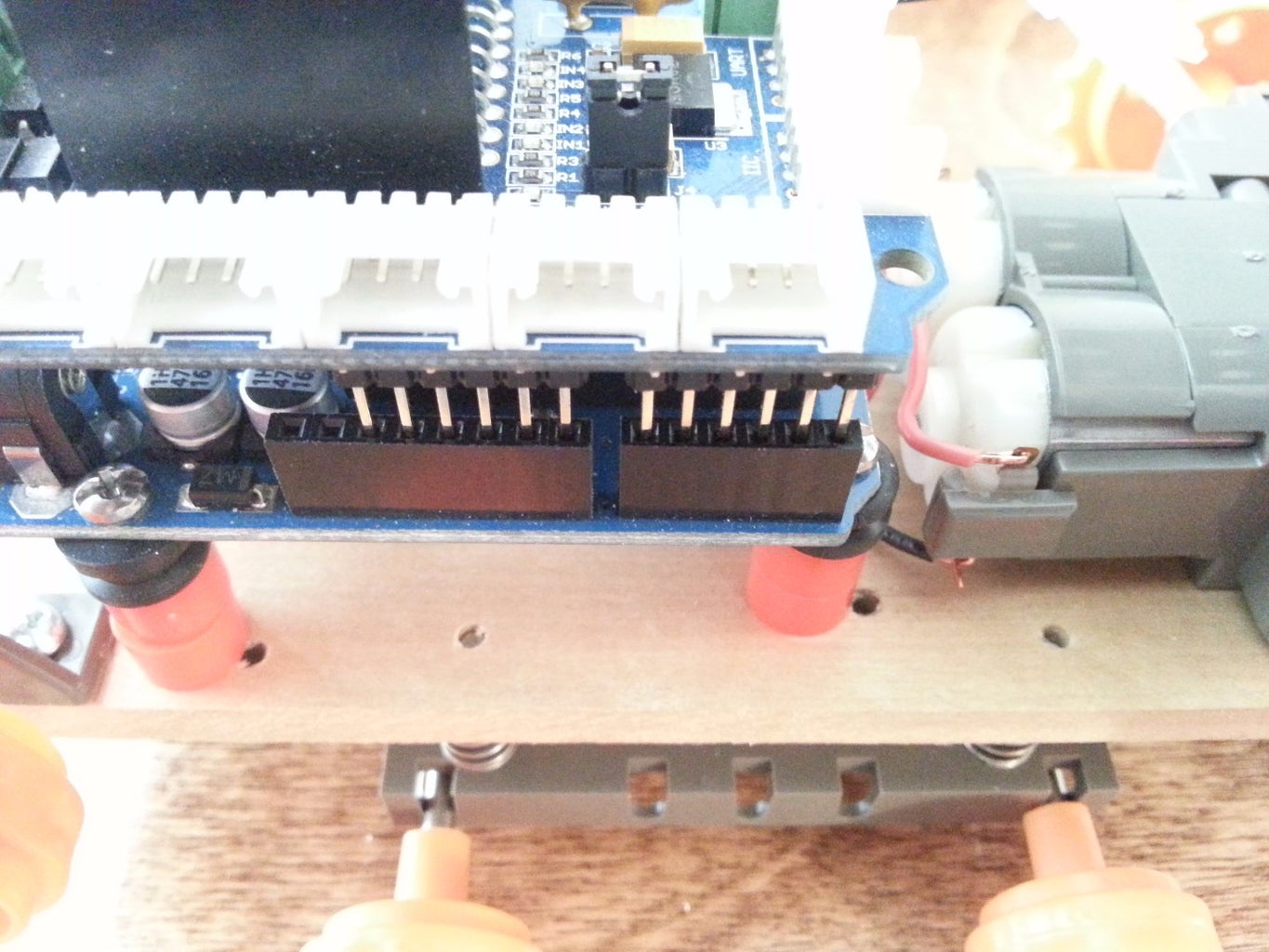


Being very careful not to bend pins, line up the pins from the Motor Shield with the slots in the Arduino and press down until the Motor Shield is secure to the Arduino.
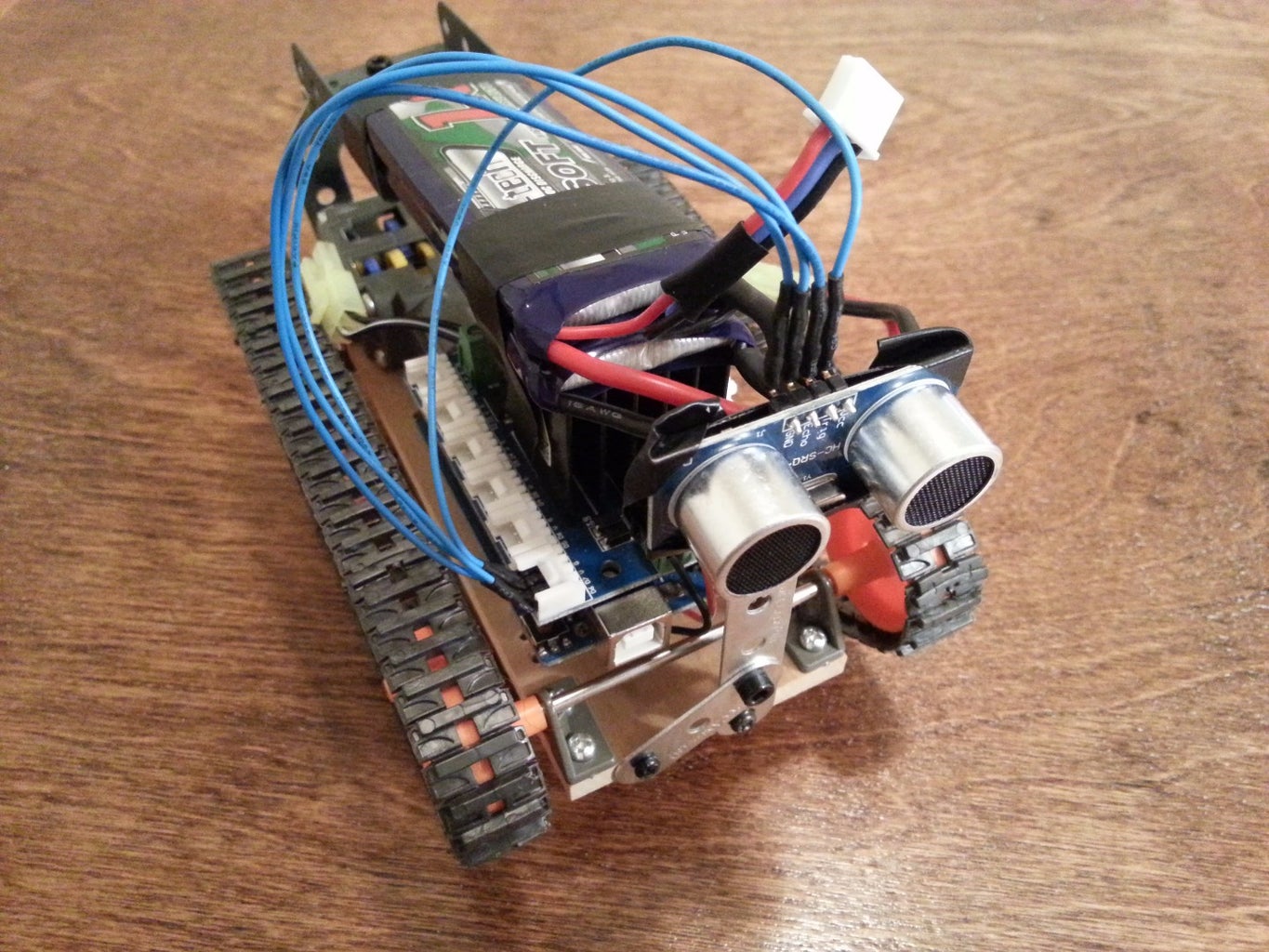
Step 17: Mount the HC-SR04 Ultrasonic Sensor

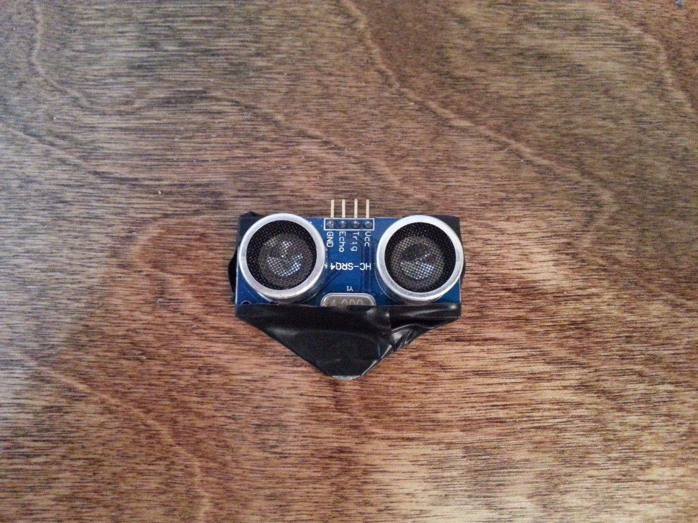


- Tape around a triangular erector set panel.
- Tape the sensor around the corners to the panel.
- Bolt a strut to the sensor triangle.
- Mark and drill holes for mounting screws.
- Bolt the sensor mount to the chassis.
Alternatively, purchase HC-SR04 bracket from Amazon.
Step 18: Wire Up the Ultrasonic Distance Sensor
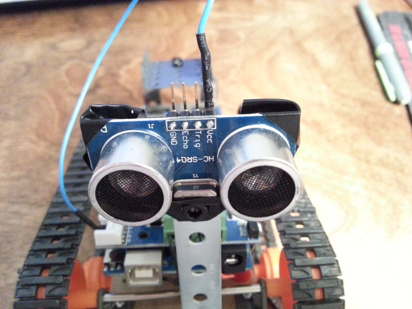


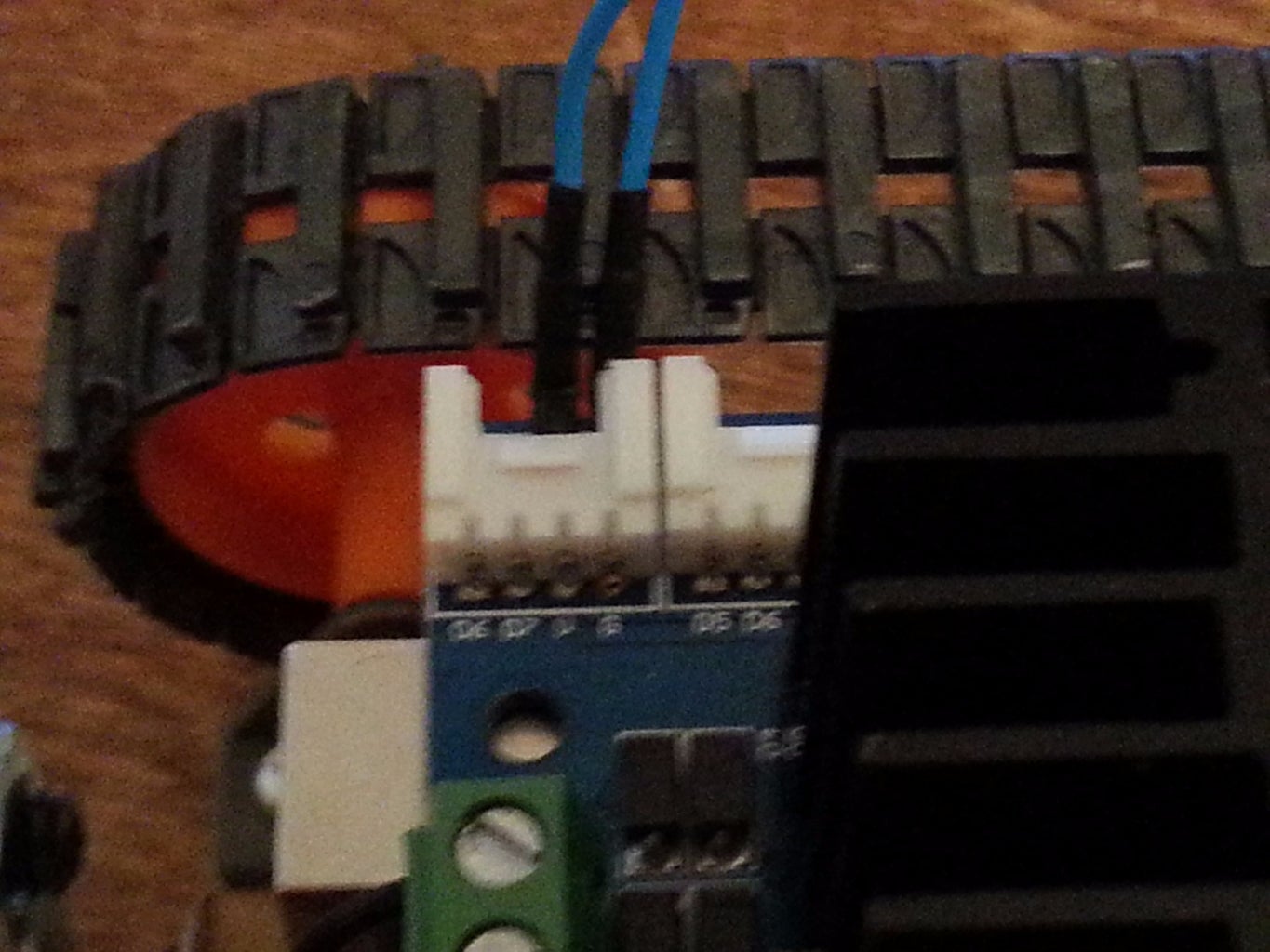

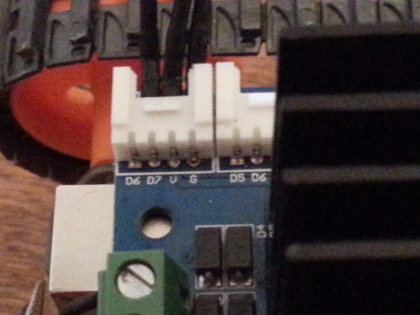


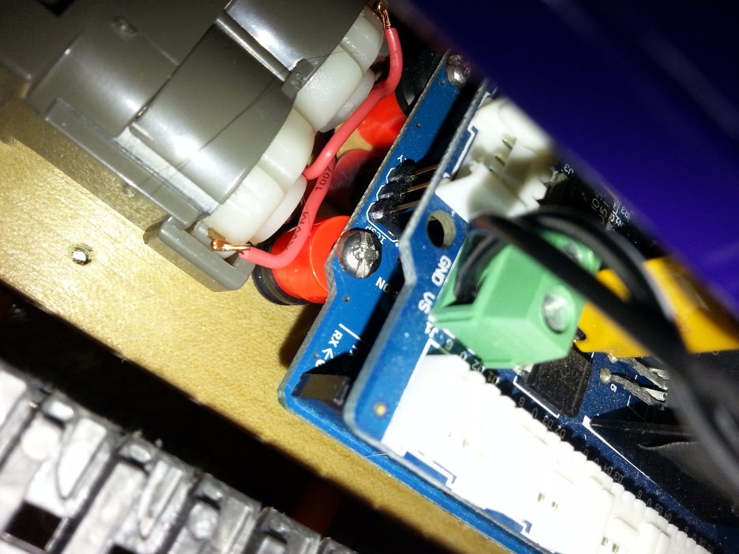
- Attach the voltage wire from the sensor, which is marked VCC, down to the Motor Shield in the foremost right position, on the pin that is marked V.
Jumper a wire from the sensor pin marked GND to the Motor Shield pin marked G.
- Jumper a wire from the Trigger pin on the sensor to the digital pin 7 marked D7 on the Motor Shield.
Jumper a wire from the Echo pin on the sensor to the digital pin marked D6 on the Motor Shield.
Using computer jumper wires negates using special cables, or regular wire could be soldered to the pins. When soldering, it is good practice to use different colored wire to avoid confusion, or when jumpering use different colored jumpers if they are available.
Refer to the above pictures.
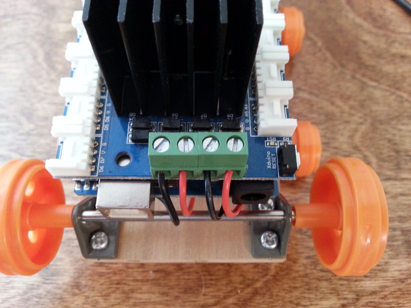
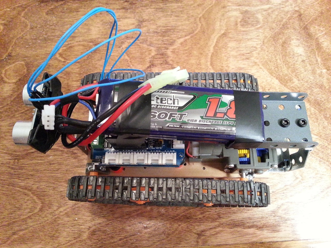
Step 19: Mount the Battery
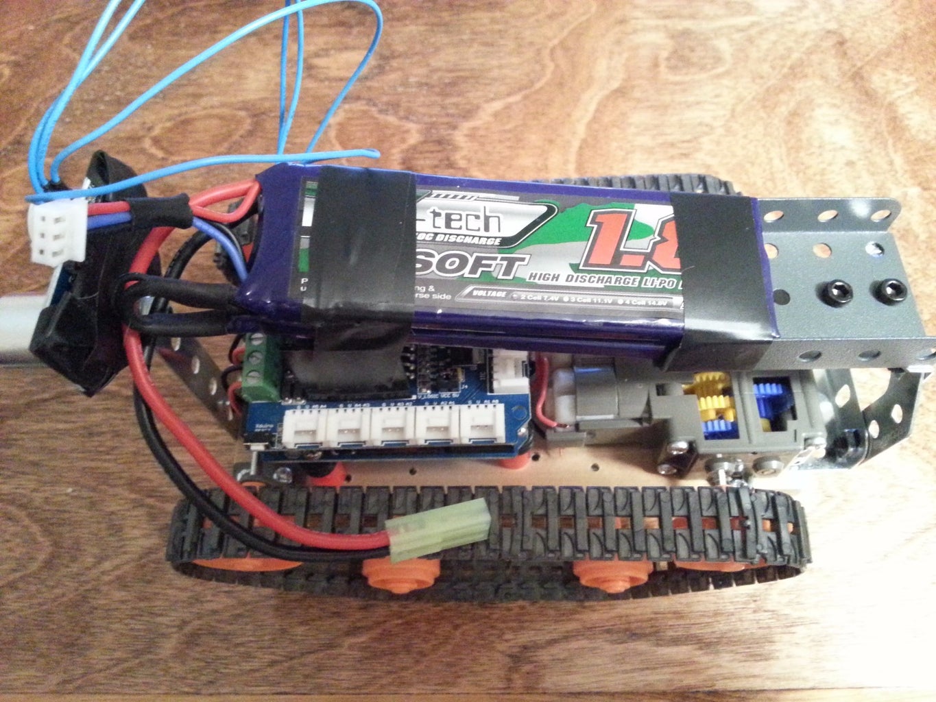


Mount the battery. Be conscious of the placement, as the battery is likely to be the heaviest of all the components on the robot. The battery holder here was mounted too far back, so it was moved forward onto the top of the motor shield heatsink for better weight distribution. Note the battery hookups on the motor shield. The red wire goes to positive, and the black to negative. Clip the battery plugs together and the Arduino and Motor Shield lights should illuminate.
Step 20: Load Your Program
Programs in the Arduino language are called sketches. Load this sample sketch and your robot will be zooming around in no time! If you have problems with the .ino file, the program is included below in bold, just copy and paste into the Arduino executable window.
//Compilation of robotics programs for use on Instructables. Thanks for everyone that contributed!
#define trigPin 7 #define echoPin 6 //#define led 11 //#define led2 10
int pinI1=8;//define I1 interface int pinI2=11;//define I2 interface int speedpinA=9;//enable motor A int pinI3=12;//define I3 interface int pinI4=13;//define I4 interface int speedpinB=10;//enable motor B
void setup() { Serial.begin (9600); pinMode(trigPin, OUTPUT); pinMode(echoPin, INPUT); // pinMode(led, OUTPUT);// // pinMode(led2, OUTPUT);//
pinMode(pinI1,OUTPUT); pinMode(pinI2,OUTPUT); pinMode(speedpinA,OUTPUT); pinMode(pinI3,OUTPUT); pinMode(pinI4,OUTPUT); pinMode(speedpinB,OUTPUT); }
void loop() { long duration, distance; digitalWrite(trigPin, LOW); // Added this line delayMicroseconds(2); // Added this line digitalWrite(trigPin, HIGH); // delayMicroseconds(1000); - Removed this line delayMicroseconds(10); // Added this line digitalWrite(trigPin, LOW); duration = pulseIn(echoPin, HIGH); distance = (duration/2) / 29.1; if (distance < 40) { // This is where the LED On/Off happens analogWrite(speedpinA,0);//Slows speed of motors to zero analogWrite(speedpinB,0);//Slows speed of motors to zero digitalWrite(pinI4,LOW);//turn DC Motor B move clockwise digitalWrite(pinI3,HIGH); digitalWrite(pinI2,LOW);//turn DC Motor A move anticlockwise digitalWrite(pinI1,HIGH); // digitalWrite(led,HIGH); // When the Red condition is met, the Green LED should turn off // digitalWrite(led2,LOW); } else { analogWrite(speedpinA,240);//Drive Forward analogWrite(speedpinB,240);//Drive Forward digitalWrite(pinI4,LOW);//turn DC Motor B move clockwise digitalWrite(pinI3,HIGH); digitalWrite(pinI2,LOW);//turn DC Motor A move anticlockwise digitalWrite(pinI1,HIGH); // digitalWrite(led,LOW); // digitalWrite(led2,HIGH); } if (distance >= 200 || distance <= 0){ analogWrite(speedpinA,240);//Drive Forward analogWrite(speedpinB,240);//Drive Forward digitalWrite(pinI4,LOW);//turn DC Motor B move clockwise digitalWrite(pinI3,HIGH); digitalWrite(pinI2,LOW);//turn DC Motor A move anticlockwise digitalWrite(pinI1,HIGH); Serial.println("Out of range"); } else { Serial.print(distance); Serial.println(" cm"); } delay(500); }
Refer to the Arduino Website for detailed instructions concerning loading programs, writing your own programs, and researching robot logic. Arduino has a huge community of people working on all aspects of the controller, any problem you are likely to encounter has most likely already been solved.

Step 21: Finished Robot!

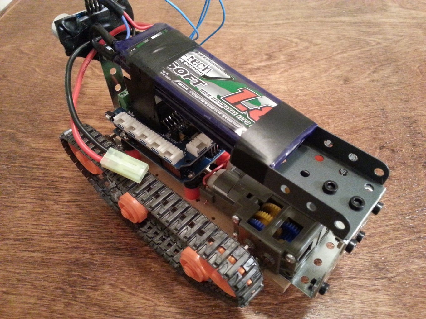
This robot will give you a great starting point for a number of robotics projects. You are limited only by your creativity! Thank you for reading this Instructable!


