

Introduction: Transforming Optimus Prime Costume


Transforming Optimus Prime Costume
Designed and constructed by Jeff Robertson The idea for this costume was inspired by my son's love of Transformers. During the first quarter of 2015, this love turned into an obsession. While discussing random real-life objects, such as ceiling fans, bulldozers, clocks, etc., he would constantly ask the question "But...can it transform?". He also began walking and talking like a robot (unfortunately no robot dancing, though). I tried to explain that Transformers are aliens and not robots; but he didn’t quite understand that concept. He also began transforming from bot-mode to vehicle-mode using only his body and a great deal of imagination. From a standing position (bot-mode), he would simply crouch down, then lay flat and extend his arms forward (vehicle mode), all while imitating the transforming sound effect. At that point, I decided that I needed to create a better means of transformation for him, and that means would eventually become a transforming Optimus Prime costume.
Step 1: DESIGN
During my initial research, I saw several well-built transforming costumes on the internet that were fully functional, but lacked the aesthetic appeal that I was looking for. For my design, I tried to focus my efforts on this aesthetic appeal of the vehicle mode while maintaining the functionality of the costume. I also realized that my son may lack the flexibility and dexterity needed for a transforming costume, so I had to ensure that the transformation was fairly easy.
When I began building and assembling the costume, I ran into several roadblocks that brought about design changes. One of the biggest road blocks dealt with the shapes of the parts. Since I wanted a semi-realistic looking vehicle mode, I designed many parts to incorporate curves and chamfered edges. This prevented me from getting the kind of transforming functionality that I was hoping for. Another big roadblock dealt with the weight and balance of the costume. Because of this issue, I had to mount the Cab and Sleeper to the Rear Fender Sub-assembly to partially support the weight of the costume (approximately 10 lbs) with the rear wheels.
Step 2: 3D PDF
After struggling with the costume that I designed and built last year using AutoCAD 2D drafting software, I decided to use Solidworks 3D modeling software for my design this year. Since this design is far more complex than last years design, the 3D software proved to be essential in the development stages. Since I modeled just about every part on this costume, I have attached a 3D pdf. This file will need to be downloaded and opened by a pdf viewing/editing software, such as Adobe Reader. However, 3D content is typically disabled by Adobe Reader. In order to enable this feature, you may have to select "Options>Trust this document always" from the top of the window. Then, you may need to right-click within the document to enable the 3d content. This 3D pdf will allow users to rotate, spin, pan, and zoom the 3D model. There is also an option to hide and show specific parts and an option to show the model tree, which contains all the parts that make up the model. For the model render mode, I suggest using the "solid outline" mode, which will make the models edges visible. There are several tutorials on the internet for navigating and using 3D pdfs, which may be helpful for those new to these types of files.
Step 3: Grille/Bumper Sub-assembly


Refer to the attached images for sub-assembly diagram, detailed part drawing, and reference images. The detailed part drawing is B size (11 x 17) and will need to be scaled accordingly to be printed.
All parts were made from single wall, B-Flute cardboard except for the following:
- Part 11: popsicle stick
- Part 69: bright aluminum screen wire
- Part 72: Sylvania DOT-it silver LED light
All parts were assembled using hot glue.
With the exception of the LED Lights and Screen Wire, all parts were primed with Artists Loft White Acrylic Gesso and then painted with Krylon Premium Metallic Original Chrome Spray Paint.

Step 4: Hood/Front Fender Sub-assembly


Refer to the attached images for sub-assembly diagram, detailed part drawing, decal drawing, and reference images. The detailed part drawing and decal drawing are B size (11 x 17) and will need to be scaled accordingly to be printed.
All parts were made from single wall, B-Flute cardboard except for the following:
Part 73: 1" diameter cardboard cylinder.
NOTE: Part 73 is the handle used to reposition this sub-assembly during transformation.
All parts were assembled using hot glue.
All parts were primed with Artists Loft White Acrylic Gesso, then painted with Craftsmart Bright Red Acylic Paint, and then finished with Krylon Crystal Clear Acrylic Coating.
The flame decals were designed in AutoCAD, colored in Photoshop, and printed on glossy photo paper. These decals were attached using Elmers permanent double-sided tape. I found this tape worked better than liquid glue, which tends to cause waves and ripples in the paper.
The wheels were 4.25" diameter bicycle training wheels. The wheel/rim area was primed with Artists Loft White Acrylic Gesso and painted with Krylon Premium Metallic Original Chrome Spray Paint. The wheels were attached to my sons forearms using padded knee wraps with velcro straps.
Step 5: Cab Sub-assembly


Refer to the attached images for sub-assembly diagram, detailed part drawing, decal drawing, and reference images. The detailed part drawing and decal drawing are B size (11 x 17) and will need to be scaled accordingly to be printed.
All parts were made from single wall, B-Flute cardboard except for the following:
Part 39 & 41A/B: clear acrylic sheet. This material was chosen for the windows to mimic glass's specular highlights and reflective attributes.
Part 75: 1" diameter wooden dowel. This can be substituted by a similar sized cardboard cylinder, PVC pipe, or similar part.
Part 47: 2" diameter cardboard cylinder.
Part 48: 1" diameter cardboard cylinder.
All parts are assembled using hot glue.
With the exception of the acrylic windows, all parts were primed with Artists Loft White Acrylic Gesso, then painted with Craftsmart Bright Red or Bright Blue Acylic Paint, and then finished with Krylon Crystal Clear Acrylic Coating.
Since the doors needed to be functional to allow my son's arms to be exposed during bot-mode, a small rectangular piece of 3/16" thick basswood was hot glued to the inside of the doors, which were then attached to the cab using 2" wide hinges to provide durability during transformations.
The flame decals were printed on glossy photo paper and attached using Elmers permanent double-sided tape.
Attachments
Step 6: Sleeper Sub-assembly


Refer to the attached images for sub-assembly diagram, detailed part drawing, decal drawing, and reference images. The detailed part drawing and decal drawing are B size (11 x 17) and will need to be scaled accordingly to be printed.
All parts were made from single wall, C-Flute cardboard except for the following:
Part 45 & 61: 3.9" diameter cardboard cylinder (mailing tube). Part 61 was cut to increase its arc length so it could fit over part 45.
Part 46: Plastic end caps that came with the mailing tubes (parts 45 & 61).
All parts are assembled using hot glue.
All parts were primed with Artists Loft White Acrylic Gesso. With the exception of parts 45, 46, 61, and 80, all parts were painted with Craftsmart Bright Blue or Black Acylic Paint and then finished with Krylon Crystal Clear Acrylic Coating. Parts 45, 46, and 61 were painted with Krylon Premium Metallic Original Chrome Spray Paint.
The flame decals were printed on glossy photo paper and attached using Elmers permanent double-sided tape. The door trim decals were printed on matte card stock paper. They were then primed with Artists Loft White Acrylic Gesso, painted with Krylon Premium Metallic Original Chrome Spray Paint, and attached using Elmers permanent double-sided tape.
Attachments
Step 7: Rear Fender Sub-assembly


Refer to the attached images for sub-assembly diagram, detailed part drawing, decal drawing, and reference images. The detailed part drawing and decal drawing are B size (11 x 17) and will need to be scaled accordingly to be printed.
All parts were made from single wall, B-Flute cardboard except for the following:
Part 77: 1/2" diameter PVC pipe.
Part 78: 3/8" wooden dowel.
Wheels: 5" diameter black bicycle training wheels. The wheel/rim area was primed with Artists Loft White Acrylic Gesso and painted with Krylon Premium Metallic Original Chrome Spray Paint.
All parts are assembled using hot glue.
With the exception of the inner section of part 77, all parts were primed with Artists Loft White Acrylic Gesso, then painted with Craftsmart Bright Red or Black Acylic Paint, and then finished with Krylon Crystal Clear Acrylic Coating. The wheel's rims were primed with Artists Loft White Acrylic Gesso and painted with Krylon Premium Metallic Original Chrome Spray Paint.
The Rear Fender Sub-assembly was attached to the Sleeper Sub-assembly using a 3" wide hinge. This allowed the Sleeper and Cab to be rotated up and rest on the rear fender sub-assembly, which partially supported the weight of the sleeper and cab.
The flame decals were printed on glossy photo paper and attached using Elmers permanent double-sided tape.
Step 8: Final Assembly


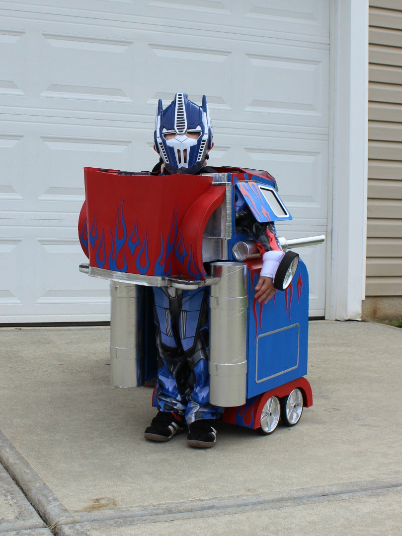


In order to maintain a temporary method of attachment between the Cab and Sleeper Sub-assemblies, I used 4 medium sized binder clips to secure these pieces together. However, these pieces could have been hot glued together for a permanent attachment. The Grille/Bumper Sub-assembly was hot glued to the Hood/Front Fender Sub-assembly. This assembly was then attached to the Cab using suspenders straps. The final assembly was attached to my son using suspender straps hot glued to the inside of the Cab.
After my son put on his store-bought Optimus Prime costume and slipped into his homemade Optimus Prime costume, it was time to "Roll Out" to go trick or treating.


Fourth Prize in the
Halloween Costume Contest 2015


