

Introduction: TurtleDuino Object Avoidance Robot


Shopping List:
- Arduino UNO (Sparkfun.com)
- Ultrasonic Ping))) Sensor (jameco.com)
- 2 Larg Servo motors continuous rotation (sparkfun ROB-09347)
- 1 Medium Servo Motor 180 Degrees rotation (sparkfun ROB-10333)
- Breadboard (sparkfun PRD-09567)
- Jumper Wires (sparkfun PRD-11026)
- SPST toggle switch (sparkfun COM-09276)
- 22 AWG hookup wire (sparkfun PRD-08023)
- Servo Motor Extensions (sparkfun ROB-08738)
- 9v battery plug jack for Arduino (sparkfun PRY-09518)
- 9v battery holder (optional)
- 9v battery
- 4 AA batteries
- Breakaway headers-long (sparkfun PRT-10158)
- An old R/C car's wheels
- 2 Large servo mounts
Home depot:
- 1/2" in. 45 degrees pvc pipe (Turrtle"s neck) (in electrical)
- 1/2" in. pvc one hole conduit snap strap or a conduit clamp (to support the turtle"s neck) (in electrical)
- 2" in. Service Entrance Cap (turtle"s shell) (in electrical)
- 1" in. Service Entrance Cap (turtle"s head) (in electrical)
- Liquid electrical tape (in electrical)
- Hot glue gun kit (in tools)
- Solder kit (in tools)
Hardware section
- 3/8"x6x24" Craft Board (to make the base of the turtle)
- #6-32x1" machine screws (about 20)
- #6 flatwashers (small bag)
- #6x1/2" sheet metal screws (to attach neck bracket, front wheels, and shell to the base)
- #4x1/2" sheet metal screws (to attach servos and arduino to the base) (small bag)
- #6 nuts (small bag) , 4 #6-32x2" long bolts (to attach head to neck and the ping servo to head)
- 90 degrees angle corner plate
- 2" painting brush (for the cool mohawk) (in paint)
Step 1: Cutting the Base


In this step were are going to cut the base, install the rear servo motors, front and rear wheels, and the 4 AA battery holder.
Remove and discard the bottom piece of the turtles shell, then place the shell on the 1/2"x6x4' poplar wood and trace the inside diameter of the shell with a 3" pencil (3" pencil because is a tight space). Leave about 2" of the base in front of the shell then cut the traced area. (see pictures) Now lets use the two servo mounts or make your own and attach the rear servo motors using the #4 sheet metal screws (make sure they are the continuous rotation ones) to the back of the base near the outside edges so that the only thing sticking out of the side is just the shaft of the servo motor. Drill a 1/4" in. hole on the base in between the 2 servos, we are using this opening to run the motor wires and the 4 AA batt. holder's "+" and "-" leads to the breadboard. Attach the front wheels I used 2 small lego pieces and screwed the into the base using the #6x1/2" sheet metal screws. I used hot glue to attach the rear wheels to the large round servo horn and then screw them to the servo shaft. And last screw in the 4 AA battery holder.(don't forget to run the wires through the 1/4" hole.
Step 2: The Turtle's Neck


Now we are going to attach the neck to the base. Grab the 1/2" 45 degrees pvc pipe and cut off the wide end of the pipe. screw in the pvc pipe bracket in the center of the front part of the base so the bracket is about two inches from the front edge. Cut the other end of the pipe in an angle see pictures, and drill through a 3/16" hole at the end of the upper side of the pipe see picture ( these holes will be use to mount the 90 degrees angle plate to the neck and support the turtles head. The holes have to be level, align and drill. from the left side of the neck to the right side of the neck.
Step 3: Building the Turtle's Head


To me building the head was one of the most difficult step in the whole project.
so bear with me on this one , I'm going to try to make it as less painfull as possible.
Grab the 1" service drop cap, remove and discard the inside piece. Plase the ping))) sensor's cylinders face to face to the head and trace around the cylinders, that's how much you're going to cut off of the front of the head. see picture.( I recommend using a dremel)
After you have cut the openings for the ping sensor place it in the head so just 1/8" is sticking out on the front of the head. Drill two 3/16" holes one on each side of the front part of the head, right above the mounting holes of the ping sensor. And then attach the ping sensor to the head using two small zipties.see picture for details. Next place the servo motor in the head and mark the mounting holes on top of the head from the inside. Drill the two servo mounting marks using a 3/16 drill bit, then attach the servo using (2) 6-32x2" bolts and (2) 6-32 nuts.
Step 4: Building the Turtles Head Part 2


Take the 90 degrees angle corner plate and attach the medium servo's horn using the hardware that comes with the servo, two screws and two sleeves. See pictures for details. screw in place the horn to the servo. Run the ping sensor and the servo's wires through the turtle's neck down to the breadboard. But first attach the servo extensions to the servo and ping so they can reach the breadboard. Now attach the corner plate to the horn and attach it to the turtles neck using one 6-32x2" bolt and nuts.
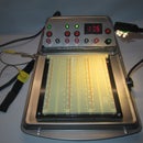
Step 5: Wiring


Start by peeling off the adjesive from the back of the breadboard and place it on the rear section of the base, right above the rear servos. Measure and cut a piece of wood 1/8" larger than the arduino. this plataform will be place on top of the turtle's neck support, using the #4x1/2" sheet metal screws. Screw the Arduino board to the plataform using the #4x1/2" sheet metal screws. Now the wiring connections, using the breakaway header pins, connect the two rear servos, ping servo and the ping))) sensor to the breadboard ( cut (4) 3-pin sections off of the header pins to connect the servos). Hook up the rear motor's power source (4 AA battery holder) negative (black) and positive (red) to the breadboard's rails, black lead to blue rail and red lead to red rail of the breadboard.
attach the left and right servo motor's red leads to the red rail and black leads to the blue rail of the breadboard.
Left motor's white lead to the Arduino's D-pin 11
Right motor's white lead to the Arduino's D-pin 10
Ping Motor: Brown is negative (ground)
Orange is positive (power)
Yellow is the signal wire
Connect the brown lead to the blue rail of the breadboard and the orange lead to the red lead of the breadboard.
Yellow wire to the Arduino's D-pin 6.
Ping sensor: Connect the pin labelled GRN on the ping sensor to the Arduino's GRN terminal.
Connect the pin labelled 5v on the ping sensor to the Arduino's 5v terminal.
and finally connect the pin labelled SIG to the Arduino's D-pin 7.
Install the 9v battery and holder.
Now grab the SPST toggle switch and solder one 8" in. lead to each terminal. Take the 9v plug jack and cut the red wire in half, then solder one lead from the switch to one end of the plug jack and the other lead from the switch to the other end of the plu jack.
Drill a 1/4' hole on the lower back section of the shell and install the switch.
Step 6: Arduino Sketch and Mohawk


The mohawk: Take the 3" in. paint brush and crazyglue, pour it at about 1 1/4" in. from the end of the brush. Soak both sides (wear some gloves) and let it dry for 20 min.. Once dried cut 1 1/2" off the end of the brush, now take that piece and glue it to the head using a pvc cement or any other plastic glue.
Plug your Arduino to your computer download the sketch below. Congratulations you have finish building the TurtleDuino.
// TurtleDuino Obstacles Avoiding Robot By:RobDavinci
#include <Servo.h> //include Servo library
const int RForward = 0;
const int RBackward = 180;
const int LForward = RBackward;
const int LBackward = RForward;
const int RNeutral = 90;
const int LNeutral = 90; //constants for motor speed
const int pingPin = 7;
const int irPin = 0; //Sharp infrared sensor pin
const int dangerThresh = 10; //threshold for obstacles (in cm)
int leftDistance, rightDistance; //distances on either side
Servo panMotor;
Servo leftMotor;
Servo rightMotor; //declare motors
long duration; //time it takes to recieve PING))) signal
void setup()
{
rightMotor.attach(11);
leftMotor.attach(10);
panMotor.attach(6); //attach motors to proper pins
panMotor.write(90); //set PING))) pan to center
}
void loop()
{
int distanceFwd = ping();
if (distanceFwd>dangerThresh) //if path is clear
{
leftMotor.write(LForward);
rightMotor.write(RForward); //move forward
}
else //if path is blocked
{
leftMotor.write(LNeutral);
rightMotor.write(RNeutral);
panMotor.write(0);
delay(500);
rightDistance = ping(); //scan to the right
delay(500);
panMotor.write(180);
delay(700);
leftDistance = ping(); //scan to the left
delay(500);
panMotor.write(90); //return to center
delay(100);
compareDistance();
}
}
void compareDistance()
{
if (leftDistance>rightDistance) //if left is less obstructed
{
leftMotor.write(LBackward);
rightMotor.write(RForward); //turn left
delay(2000);
}
else if (rightDistance>leftDistance) //if right is less obstructed
{
leftMotor.write(LForward);
rightMotor.write(RBackward); //turn right
delay(2000);
}
else //if they are equally obstructed
{
leftMotor.write(LForward);
rightMotor.write(RBackward); //turn 180 degrees
delay(2000);
}
}
long ping()
{
// Send out PING))) signal pulse
pinMode(pingPin, OUTPUT);
digitalWrite(pingPin, LOW);
delayMicroseconds(2);
digitalWrite(pingPin, HIGH);
delayMicroseconds(5);
digitalWrite(pingPin, LOW);
//Get duration it takes to receive echo
pinMode(pingPin, INPUT);
duration = pulseIn(pingPin, HIGH);
//Convert duration into distance
return duration / 29 / 2;
}
I hope this instructable was fun to you as it was for me while building it. If you need additional help let me know and I'll be more than happy to help you build your robot.
Step 7: Vote for This Little Guy in the Arduino Contest
Hello, TurtleDuino got accepted in the Arduino contest please vote for the little guy . Thank you !!
Step 8: Wiring


Participated in the
Arduino Challenge


