

Introduction: Twitch - Your Robotic Pet


This instructable will show you how I built "Twitch". Twitch is a virtual pet that is able to express itself through it's eye, movements, and the sounds it makes, which happens to be sound clips from some of its favorite movies. It can be happy, sad, angry, or neutral depending on how much you interact with it.
Twitch evolved from a project I saw on the Adafruit site called Adafriend the Virtual Pet Cube by John Wall. The original project consisted of an Adafruit Pro Trinket, a LED Matrix and backpack with a 3d printed cube body among other things. I already had an Arduino Uno, and wasn't interested in getting it 3d printed so the project evolved from there.
I used much of the code from the original project, as I liked the animated eye and the different emotions it was able to portray. From there I added a pan/tilt base, capacitive touch sensor and an Adafruit Wave shield to give my pet the voice I was looking for.
In order to successfully complete this project, you should have decent soldering skills. It would be helpful if you have completed at least one Arduino project before, so that you have gotten through setting up the Arduino software and are able to upload sketches to it successfully. You should also have some experience with debugging code, as mine is far from perfect.
Step 1: Required Parts
- Arduino Uno
- Adafruit Wave Shield 1.1
- Mini Pan Tilt kit with 2 servos
- 1.2" LED Matrix and backpack
- Capacitive touch pad sensor - I used a 5 pad, but a single pad would work just fine.
- A speaker to play the audio files
- An SD card to hold your sounds
- Power supply for the Arduino. The servos draw too much power to run from 5V USB
- A breadboard or proto board
- A box to hold the electronics - I used a 4X4X3 wooden box I got from Michael's
- Wires, solder, and the usual
Step 2: Preparation - the Arduino Wave Shield, LED Matrix and Pan Tilt

Follow the instructions to build the Wave shield. Copy at lease one file to your SD card and make sure you can successfully run the dap_hc sketch (see next step for information on properly formatting the file). Use the serial output to assist in debugging. The output will indicate available RAM, as well as directory and file names it finds and then play them. Although I feel that my soldering skills are pretty decent, I had trouble with this one and had to go over each solder joint a second time until I got it to work. Solder the speaker to the speaker pins near the headphone jack on the shield.
Then solder the LED matrix to the backpack. Note that it is important that you solder it the correct way. I put it upside down the first time. The Backpack library comes with an example sketch. Make sure you can run that sketch successfully before proceeding.
Build the pan tilt kit assembly. You will find that the LED matrix backpack fits into the pan tilt base reasonably well.
Step 3: Preparing the SD Card
The project uses wave files played with the wave shield to help convey its 4 emotional states, sad, happy, angry, and neutral as well as sounds for when the touch sensor is activated. I used about 10 different sound clips from different movies to represent each state, but you can choose songs, animal noises or whatever you want. I got mine from a site called www.moviewavs.com, which I have been using since the late 1990's. Although it is not updated as frequently as it once was, I would highly recommend it.
Although the Wave shield supports 8.3 file names for your files, I names all the files with 2 numbers to save memory. I am sure there is a more efficient way to do this, only I couldn't work it out.
Make sure the sample rate is mono, 22KHz (or less) and 16-bit (or less) or they will not play. I used the open source software Audacity to convert them to the correct format, although there are several other ways to do it as specified in this guide.
I collected several files I wanted to use, organized them into the appropriate emotional states and renamed them as references in the code.
Touch sounds are named
1.WAV - 8.WAV
Neutral sounds
10.WAV - 19.WAV
Angry sounds
30.WAV - 39.WAV
Sad sounds
50.WAV - 59.WAV
Happy sounds
70.WAV - 79.WAV
Copy these sounds to the root directory of your SD card, then insert it into the Wave shield.
Step 4: Wiring It Together
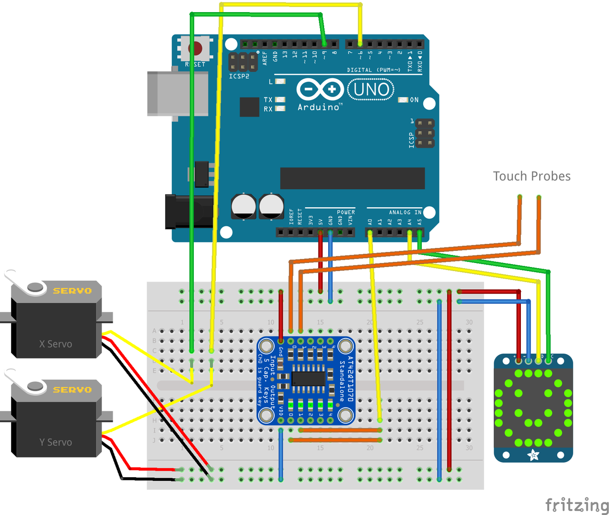


Follow the image to help you wire it all up. The Fritzing library (Software used to create the drawing) does not include an image for the wave shield, but just use the same pins. The wave shield uses pins 10,11,12, and 13 to communicate with the SD card, and 2,3,4 and 5 for the DAC (digital audio converter), so we cannot use those pins for anything else.
Pins A4 and A5 on the arduino are the I2C lines that communicate with the LED matrix. A4 connects to SDA labeled "D" (Data) on the board, and A5 to SCL labed "C" (clock) on the board.
Digital pins 6 and 9 are used to control the servos. 6 is connected to the "X" servo (up and down) and 9 is connected to the "Y" servo (left and right).
Pin A0 is connected to both outputs of the capacitive touch sensor board. If you use a single touch sensor, you would just connect both probes (or antennas) to the input line on the breakout board, and the output would connect to A0.
Step 5: Code

The code uses the SoftwareSerial library, as the Wave player causes a conflict with the Timer on the Arduino, so you will need to install and use that library to get it to work. If you are familiar with the standard servo library, It works exactly the same, although it requires you to call "SoftwareServo::refresh()" every 50ms to update the servos. You will see it in the code.
The program also uses the adafruit LED backpack and GFX libraries for the LED matrix.
The code is pretty well commented.
Instructables kind of mangled my code, so here is a link to the Github repository.
Step 6: Possible Next Steps
I am fully aware that some of my code is pretty mangled, and that it could really use some optimization. I would really like to be able to fix the hard-coded wave file names, and to use the random number directly to create the filename to play, rather than having to code the filename for each action. Unfortunately I havent had too much luck with that.
I would also smooth out the servo movements to follow the eye movements closer rather than move after the fact. I have made decent progress on that front, although it is not quite there yet. If anybody has some proper coding skills, drop some ideas in the comments.
From here you can certainly customize your project even further. You could add different sensors or create different actions or emotions. If you dig into the code a bit, you can probably figure out how to change how often your pet speaks, or when his emotions change.
In previous versions of this project, it had an IR sensor and receiver, and you could interact with it that way, and it was able to turn off the TV if you ignored it too long. Quite honestly, that ended up not being too much fun for anyone, and a Timer conflict caused a significant amount problems adding other features.
I would also consider adding a small mono amplifier, as the sound output is a little quieter than I'd like.

Runner Up in the
Microcontroller Contest 2017


