

Introduction: Two Wheel Self-Balancing Robot

This instructable will go through the design and build process for a self-balancing robot. As a note, I just want to say that self-balancing robots are not a new concept and they have been built and documented by others. I want to use this opportunity to share with you my interpretation of this robot.
What is a self-balancing robot?
A self-balancing robot is a system that uses inertial measurement data, gathered from an onboard sensor, to continuously adjust its position to keep upright.
How does it work?
A simple analogy to consider is an inverted pendulum. Where the centre of mass is above the pivot point. However, in our case, we are restricting the pendulum to 1 degree of freedom by having one axis of rotation, in our case the axis of rotation of the two wheels. Since any sort of disturbance will cause the robot to fall, we need a method of actively keeping the robot balanced. This is where our closed-loop algorithm (PID controller) comes into play, knowing which direction our robot is falling we can adjust the direction of rotation of our motors to keep the system balanced.
How does the closed-loop algorithm work?
The basic principle in keeping the robot balanced is, if the robot is falling forward it will compensate by move the bottom of the robot forward to catch itself and therefore keep vertical. Likewise, if the robot is falling backwards it will compensate by moving the bottom of the robot backwards to catch itself.
So, we need to do two things here, first, we need to calculate the angle of inclination (Roll) that the robot is experiencing and as a result, we need to control the direction of rotation of the motors.
How will we measure the angle of inclination?
To measure the angle of inclination we will be using an Inertial Measurement Unit. These modules incorporate an accelerometer and gyroscope.
- The accelerometer is an electromagnetic device that measures the proper acceleration, this is the acceleration of a body in an instantaneous rest frame.
- A gyroscope is an electromechanical device that measures angular velocity and is used to determine the orientation of the device.
However, the problem with using such sensors is that:
- The accelerometer is very noisy but is consistent over time, the angle varies with sudden horizontal movements
- The gyroscope value, on the other hand, will drift over time, but initially, it is fairly accurate
For this instructable, I am not going to implement a filter instead ill be using the onboard Digital Motion Processing (DMP). Others have used a complementary filter to get a smooth signal, you can choose whichever method you like. as the robot balances with either implementation.
Supplies
Parts:
- Arduino Pro Mini 3.3V 8 with an 8 Mhz ATMEGA328
- FT232RL 3.3V 5.5V FTDI USB to TTL serial adapter module
- GY-521 module with MPU-6050
- A pair of N20 micro gear motor 6V - 300rpm
- L298N motor driver
- LM2596S DC to DC buck converter
- Battery (Rechargeable 9.7V Li-ion battery pack)
- Battery strap
- Two prototyping PCB circuit boards
- Male and female header pins jumper wires
Tools:
- Soldering iron and solder
- Nylon hex spacer standoff
- Precision screwdriver set
- 3D printer
Step 1: Construction
Since I had access to a 3D printer I decided to 3D print the chassis and use standoffs to connect everything together.
The robot consists of 4 layers
- The bottom layer connects the motors and has mounting points for the L298N motor driver module
- The next layer houses the prototype board with the Arduino pro mini and headers soldered to it
- The third layer mounts the IMU
- The top layer, which I call the “bumper layer” hols the battery, the buck converter, and a monetary switch
My main design principle was to keep everything modular. The reason for this was if something went wrong with one of the components I could easily replace it or if I needed a component for another project I can easily take it without worrying about not being able to use the system again.


Step 2: Wiring
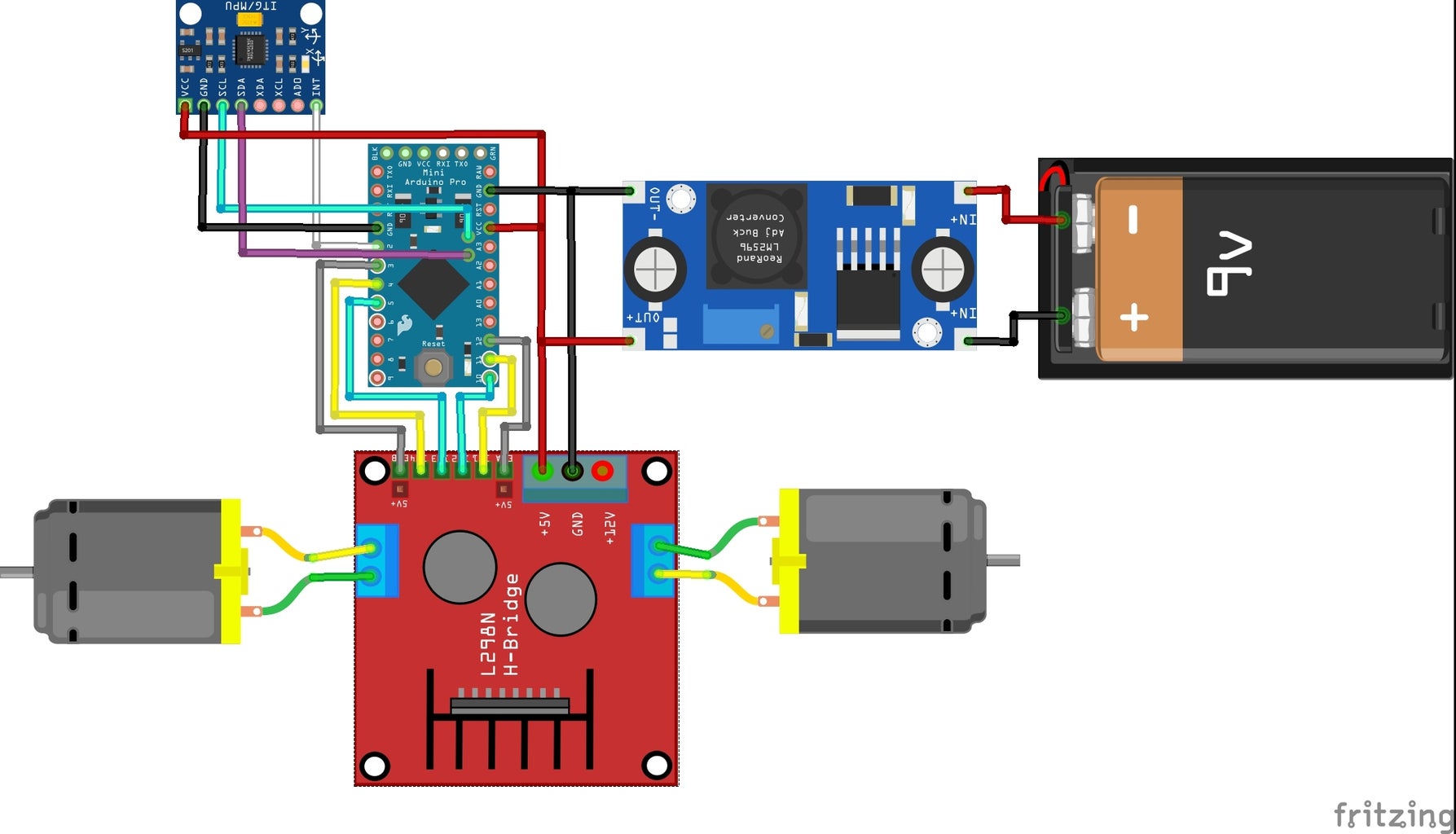
I soldered some female header pints to a perf-board to match up with the Arduino pro mini header pins. Following this, I soldered male header pins the board to allow access to the I/O. The rest of the components were mounted to the 3D printed frame and connected using jumper wires.
Step 3: Control Theory
Now we move on to the core of the project. In order to keep the robot balanced, we need to generate an appropriate control signal to drive the motors in the correct direction and at the correct speed to keep the robot balanced and stable. To do this we will use a popular control loop algorithm known as a PID controller. As the acronym suggests there are three terms to this controller, these are the proportional, integral, and derivative terms. Each of which is accompanied by coefficients that determine their influence on the system. Often the most time-consuming part of the implementation of the controller is the tuning of the gains for each unique system to get the most optimal response.
- The proportional term directly multiplies the error to give an output, so the bigger the error the bigger the response
- The integral term generates a response based on an accumulation of the error to reduce the steady-state error. The longer the system is unbalanced the fast the motors will respond
- The derivative term is the derivative of the error that is used to predict the future response and in doing so it reduces the oscillation due to overshooting the steady-state.
The basic principle of this algorithm is to continuously calculate the angle of inclination which is the difference between the desired position and the current position, this is known as the error. It then uses this error values and calculates the sum of the proportional, integral, and derivative responses to get an output, which is the control signals that are sent to the motors. As a result, if the error is large the control signal sent to the motors will rotate the motors at high speed to get to a balanced state. Likewise, if the error is small the control signal will rotate the motors low speed to keep the robot balanced.
Step 4: Using MPU 6050
MPU6050 Library
https://github.com/jrowberg/i2cdevlib/tree/master/...
Calibrating offsets
Not all sensors are exact replicas of each other. As a result, if you test two MPU 6050 you may get different values for the accelerometer and gyroscope when placed still on the same surface. To overcome this constant angle offset we need to celebrate each sensor we use. Running this script:
https://www.i2cdevlib.com/forums/topic/96-arduino-...
written by Luis Rodenas, we will get offsets. The offset errors can be eliminated by defining the offset values in the setup() routine.
Using the Digital Motion Processor
The MPU6050 contains a DMP (Digital Motion Processor).
- What is a DMP? You can think of the DMP as an onboard microcontroller that processes the complex motion from the 3-axis gyroscope and 3-axis accelerometer on board the mpu6050, using its own motion fusion algorithms. Offloading the processing that would otherwise be done by the Arduino.
- How to use it? To figure out how to use the DMP go through the example sketch MPU6050_DMP6 that comes with the MPU6050 library (in the Arduino IDE: File->Example->MPU6050->MPU6050_DMP6). This is also a good opportunity to check your sensor actually works and the wiring is correct.
Step 5: Coding
I used the Arduino IDE and an FTDI interface to program the Arduino pro mini.
Using the example sketch(MPU6050_DMP6) that comes with the MPU6050 library as my base code I added a PID() and MotorDriver() functions.
Add the library
- MPU6050: To use the MPU6050 sensor we will need to download the I2C developer library from Jeff Rowberg and add it to the Arduino “libraries” folder in found in the program files on your computer.
- Wire: We also need the Wire library to allow us to communicate with I2C devices.
Pseudo Code
Include Libraries:
- Wire.h
- MPU6050
- I2Cdev.h
Initialise variables, constants, and objects
Setup ()
- Set pin mode for controlling motors
- Set pin mode for the status LED
- Initialise the MPU6050 and set offset values
PID ()
- Calculate PID value
MotorDriver(PID response)
- Use PID value to control speed and direction of the motors
Loop ()
- Get data from DMP
- Call PID() a MotorDriver() functions
Attachments

Step 6: PID Tuning Procedure
This is the most tedious part of the project and requires a little patience unless you get very lucky. Here are the steps:
- Set I and D term to 0
- Holding the robot, adjust P so that the robot just starts to oscillate about the balance position
- With P set, increase I so that the robot accelerates faster when off balance. With P and I are properly tuned, the robot should be able to self-balance for at least a few seconds, with some oscillation
- Finally, increase D reduce the oscillation
If the first attempt doesn’t give satisfactory results, repeat the steps with a different value of P. Also be aware that you can fine-tune the PID values afterward, to further increase the performance. The values here are dependent on the hardware, don't be surprised if you get very large or very small PID values.
Step 7: Conclution
The micro gear motors used were to slow to react to large disturbances and given the system was too lightweight there was not enough inertia to get the desired pendulum effect, so if the robot leans forward it would just lean at an angle and race forwards. Finally, 3D printed wheels were are a bad choice as they keep slipping.
Suggestions for improvement:
- Faster motors with higher torque, i.e. for DC motors is higher the voltage rating the higher torque
- get a heavier battery or just move the mass a bit higher
- Replace 3D printed wheels with rubber ones to get more traction


