

Introduction: Two Chip Frequency Meter With Binary Readout


using twelve light emitting diodes. The prototype has a CD4040 as counter and a CD4060 as the timebase generator. Gating the signal is by a resistor - diode gate. CMOS ics used here allow the instrument to be powered by any voltage in the range of 5 to 15 volts, but the maximum frequency is limited to about 4 MHz.
The 4040 is a twelve stage binary counter in a 16 pin package. The 4060 is a fourteen stage binary counter and oscillator, in the same 16 pin package.
The 74HC or 74HCT versions of these chips may be used for a higher frequency range, but the supply voltage range is then limited to a maximum of 5.5 volts or so.
In order to use this in order to display the frequency of a typical HAM transmitter, some sort of a prescaler and a preamplifier will be needed. Hopefully these shall be the subject of a subsequent instructable.
Step 1: Twelve LED Array

I started on this project in order to have a simple frequency counter which would work with the minimum of hassle, using the fewest number of components and NO programming. I settled on this "two chip frequency counter" design because its simplicity was appealing.
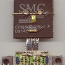
The first step was to wire the counter and make it work. I rounded up a number of red 3mm leds from my junk box and various boards and soldered them up in line on a sliver of circuit board - the result is shown here next to the counter chip. This particular ic was extracted from another half-finished project, with the fervent hope that at least this one will end up finished.
The 74HC4040 will be a better choice if you are planning on building this. It can count to a higher frequency.
Step 2: Starting the Rats Nest

It was decided to build it as small as possible, and so there is no circuit board. The leads of the 4040 was cropped, and a 100n ceramic multilayer capacitor connected across its power supply leads. This is to enable it to survive ESD better.
Wires (from CAT-5 cable) was then soldered to the stubs of the leads. After one side was so treated, it was time to test whether the chip was still alive.
Step 3: Testing the 4040

The LED and chip were introduced to each other, and a quick check, applying power to the chip and grounding the common of the LEDs, gave me blinking LEDs when the clock input of the chip was touched with a finger - it was counting the 50 Hz mains hum.
One LED was too bright - it was making the others seem too dim by comparison. It was ruthlessly pulled out, then tenderly laid aside for possible use solo.
LEDs are fragile devices and easily fail if overheated while the leads are stressed. I had to replace about three in my array. If you are buying them, be sure to get a few extra. If you are scrounging them, be sure to get a lot extra since you need them somewhat similiar in brightness.
Step 4: The Counter - Complete

The picture shows the completed counter and display. There are twelve LEDs, the counter chip, supply bypass capacitor and two resistors. The 1K resistor sets the brightness of the display. The 4.7 K resistor connects the reset input to ground. The unconnected pin next to it is the clock input.
Step 5: Cabinet for Counter

The metal cladding from a D cell was unwrapped and formed around this assembly. Plastic film was used to prevent short circuits.
The movie shows my test of the counter. It is counting 50 Hz signal provided by my finger.
Attachments

Step 6: The Time Base - Parts

A frequency counter works by counting the signal pulses for a known time, and displaying this count. A counter forms one half of the frequency counter. A circuit to deliver an accurately known interval - the timebase - is the other part.
This function is carried out by the CD4040, an oscillator and 14 stage binary devider in an 18 pin package. In order to make it fit, not all divider outputs have been brought out.
I decided on an oscillator frequency of 4 MHz - it was the most suitable one I had in my junk box. This choice of crystal means that the frequency readout will be in a multiple of a megahertz.
Step 7: The Crystal Oscillator

The 4 MHz crystal oscillator for the timebase is taking shape. A 10 Meg chip resistor sits across the two oscillator pins, and the two 10 pf capacitors are fixed on to a scrap of circuit board together with the crystal.
Step 8: Oscillator - Divider

This is the completed timebase. The red wire connects the most significant output (Q13) to the reset input. This causes a short reset pulse to appear on this pin every 8192 vibrations of the crystal. The next output (Q12) will have a square wave on it, and this is used to enable the counter while low, and to display that count when high.
I do not have any circuit diagrams as yet. This is a rough idea of how the frequency counter should operate, and the gating and display arrangements were in a state of flux as I strove to find a minimum component solution.
Step 9: Testing the Timebase

Now, testing it is a very involved process. I'll have to take it to work. Then promise that guy working (that's what he claims to be doing) with the oscilloscope, heaven, earth and beer for a chance to use it. That third, however, is fairly safe as he is rarely out of there the time the rest of us do.
Then be quick, nip in while he is out getting lunch and test the circuit, and nip out quick before he comes back. Else I might have to help him out on whatever hole he has gotten himself into and maybe miss lunch.
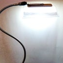
It's much simpler to use a radio. A cheap, medium wave, pocket radio that was all the rage before the newfangled mp3 gadgets came along. This little timebase will create hash all over the dial when it is working.
Using it and a few cells I was able to ascertain that the timebase worked with three cells, and that it did not work on two cells, thus establishing that at least 4.5 volts would be required to fire up my frequency counter.
Step 10: Space for Timebase

This shows the space inside the counter reserved for the timebase circuit.
Step 11: Integration

This shows the two integrated circuits in position. The "glue" logic needed between them in order to make them work as a frequency counter will be realised by diodes and resistors.
Another decoupling capacitor was added across the timebase chip. You can't have too much of decoupling. I intend this to get used close to sensitive receivers, so any noise has to be suppressed close to the source and prevented from escaping.
Hence the recycled tinsheet cabinet.
Step 12: Integration Phase Two

I changed my mind again, and the arrangement in this picture is a little different. It is more compact, and so was preferred.
Step 13: The Circuit Diagram

Now, when the construction is nearly done, here is a circuit diagram. When I finally settled on how it was going to be done, and set it down on paper, featurisms started creeping in. I could make it work as a counter too, with a switch and two additional components. So now it is a Counter / Frequency counter.
A short pulse on Q13 resets both counters.
Then Q12 will be low for a certain amount of time (2048 xtal cycles) and during that time the incoming signal clocks the 4040. The transistor is off, so the leds do not light.
Then Q12 goes high and the signal then does not get through to the input of the 4040. The transistor turns on and the count in the 4040 is displayed on the LEDs for all the world to see. Again after 2048 clocks Q12 goes low, Q13 goes high and would remain there, except that it is connected to the reset inputs of both counters, so both counts get cleared which clears the state of Q13 and so the cycle starts afresh again.
If it is set as a counter, the 4060 is held permanently in reset and the transistor switched on full time. All input gets counted and is immediately displayed. The maximum count is 4095 and then the counter starts from zero all over again.
That zener diode is delibrately made of a higher voltage than the normal supply voltage. It does not coduct during normal use. If, howvever, a larger than normal voltage gets applied, it will limit the voltage to the two chips to a value they can handle. And a really high voltage will cause that 470 ohm resistor to burn up, still protecting the electronics - well, most of them, anyway. At least, that's what I hope is going to happen, should this thing get connected directly to the mains.
Step 14: Freq / Count Switch
A small switch was fitted to select between the two modes, plain counting of the incoming pulses versus counting them for a period and determining the frequency, and sundry other tidying up was done.
Some of the wiring has been smothered in plastic to make them short-resistant (I hope). Soldering another tinplate from another D cell across the top will make the box complete and protect the innards from stray bits of wire and globs of solder, both of which abound on my worktop.
Step 15: Back View

The swich to select between Frequency and count modes can be seen in this Back view.
Step 16: The Completed Instrument

This is a view of the completed instrument. The LEDs show the frequency weighted as follows:
2 MHz
1 MHz
500 KHz
250 KHz
125 KHz
62.5 KHz
31.25 KHz
15.625 KHz
7.8125 KHz
3.90625 KHz
1.953125 KHz
0.9765625 KHz
You have to add together the weights of the lit leds in order to read the frequency.
Some data on current consumption: at an applied supply voltage of six volts (four AA cells) the current drawn was 1 mA in Counter mode, and 1.25 mA in Frequency mode, with nothing displayed. When displaying counts (some LEDs lit) the consumption jumped to around 5.5 mA in counter mode, and 3.5 mA in frequency mode.
The counter stopped counting if the frequency was increased to above about 4 MHz. This is a little dependent on the amplitude of the applied signal. It requires full CMOS compatible input for it to count reliably. Some sort of signal conditioning is therefore nearly always necessary. A preamp and prescaler at the input will both extend the frequency range and increase sensitivity.
More on this topic can be found for searching for the words "two chip frequency counter" without the quotes.


