

Introduction: UArm Miniature Palletizing Robot Arm for Arduino


Back in 2014 I bought a Miniature Palletizing Robot Arm for Arduino online, I was also beginning to experiment with 3D printing. I began reverse engineering the arm I bought and researching when I cam across David Beck doing the same thing over on Makerbot's Thingiverse site. We began working together towards our common goal of an affordable, easy to make, DIY, Open Source Robotic Arm (Lite Arm i2).
I am porting over a better version of the assembly instructions to this site as I am going to do another run of these in my online store Tesla Robotics & Electronics.
You can 3D Print these arms yourself from the parts manifest here; Open Source Robotic Arm (Lite Arm i2)
We also have a Google+ group for collaboration and learning here; Lite Arm Google +
This model was a set of "Bubblegum" uArms whose proceeds were donated to charity.
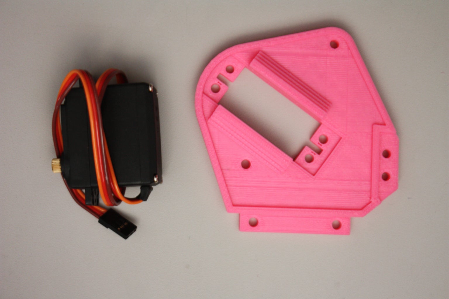
Step 1: All 3D Printed Parts, Hardware, Servos.

Make sure you have all of the 3D printed parts shown, 39 in total, in addition you will also need the following:
Servos:
Compatible with Tower Pro MG995 or MG996 Servos [x3]
- 1x Base rotation
- 2x Arm movement
- Compatible with an optional Tower Pro SG92R [x 1] (Fits in Head)
Hardware:
- Assembly will require #6M machine screws w/nuts and lock nuts.
- Assembly will require #6M flat washers.
- Assembly will require 3x 1.5" Deck or Drywall screws.
- Assembly will require 6~7" #6M threaded rod.
Mounting holes will accommodate an Arduino UNO
** 4 of the base servo’s small spacers may require sanding in order to fit (Depending on servo used). No other part tooling is required. 2 extra small spacers are included.
! Do not over tighten parts, this may cause damage to the uArm and keep it from operating properly !
Assembled Dimensions:
Height: Approximately 12 Inches (Highest position)
Length overall: 19.5 Inches with arm completely out stretched (Longest position)
Arm length: 13.25 Inches with arm completely out stretched (Longest position)
Width: 6.5 Inches at widest point with Tower Pro MG995 Servos
Width without servos: 4.5 Inches.
Width, Base: 4 Inches x 4 Inches
Base mounting holes: 4.5 inches, measured across.
Step 2: Assembly: Step 1

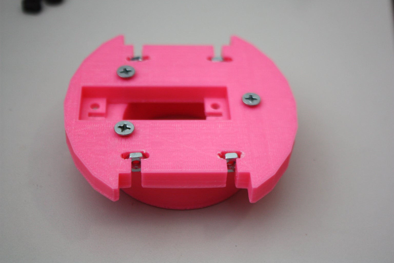
- Press the #6 nuts into the grooves as shown with a pair of pliers, this will keep them from free spinning when assembling the sides later on.
- Attach the ring to the Base as shown.
Step 3: Assembly: Step 2
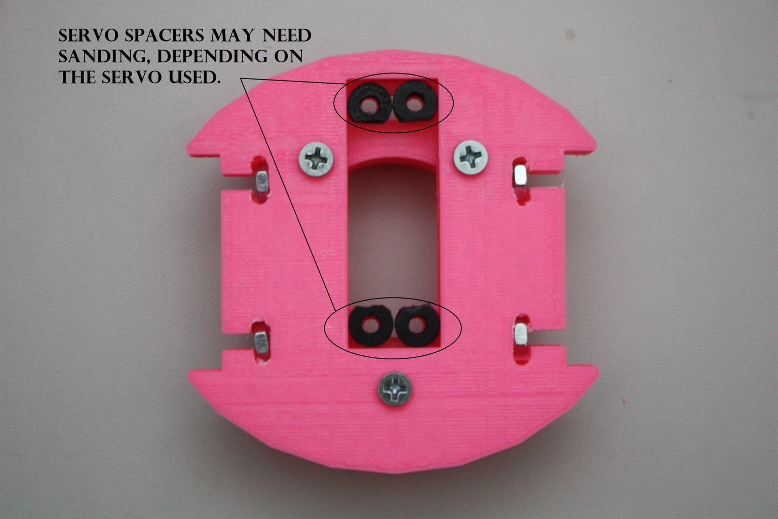

- Insert spacers in to uArm base. Spacers may need to be sanded for fit depending upon servo used.
- Install MG995 or compatible servo on top of the spacers and secure with 1/2 inch #6 machine screws.
Step 4: Assembly: Step 3


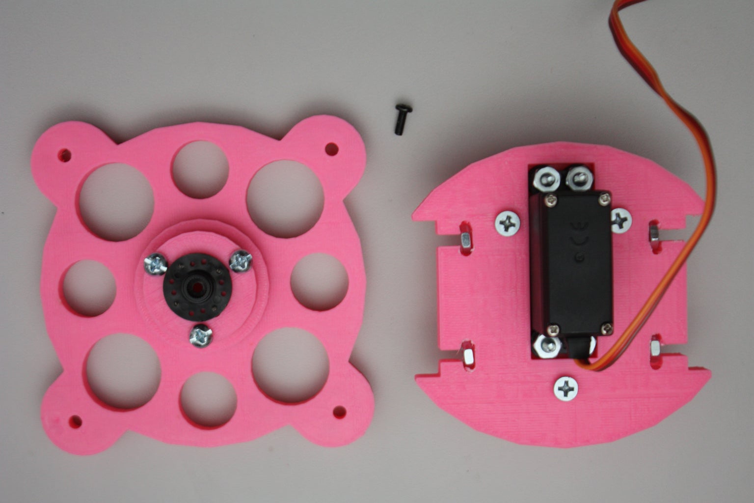
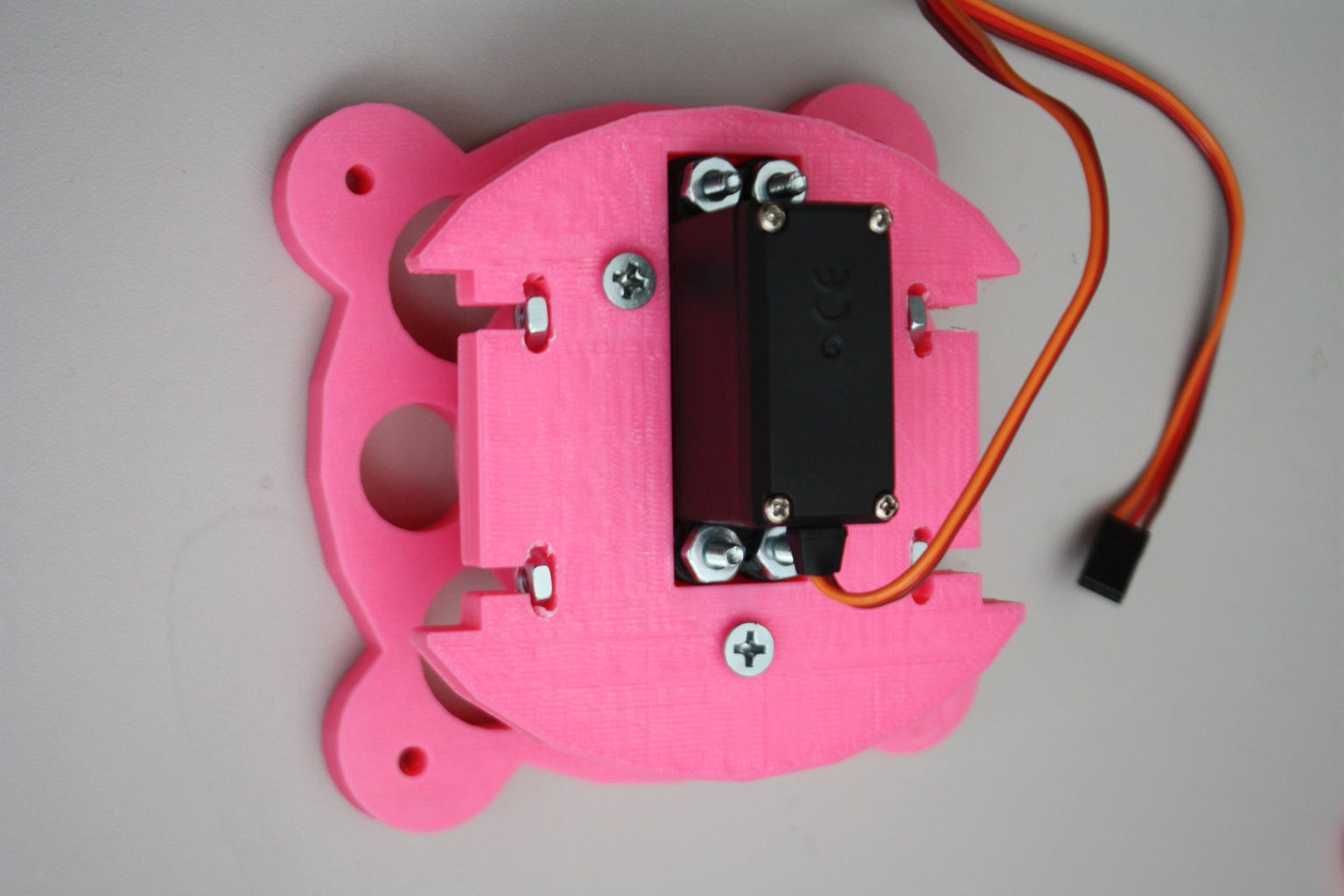
- Assemble the base stand with the spacer and servo horn mount using 3x 1" #6 machine screws as shown.
- Attach the servo horn with screws through the servo horn mount.
Step 5: Assembly: Step 4
- Attach the uArm base to the Base Stand from the previous steps with the servo horn machine screw as shown.
Step 6: Assembly: Step 5


Use the smaller shoulder in this assembly.
- Attach the MG995 or compatible servo through the small shoulder with the servo body facing outwards using 4x 1/2 " #6 machine screws.
Step 7: Assembly: Step 6


- Attach one of the printed linkage connectors to the servo horn using screws.
- Next attach the linkage connector assembly to the servo using the servos machine screw.
Step 8: Assembly: Step 7

Use the larger shoulder for this portion;
- Attach the MG995 or compatible servo through the large shoulder with the servo body facing outwards using 4x 1/2 " #6 machine screws.
Step 9: Assembly: Step 8


Assembly of the lower arm;
- You will need the parts shown above, along with 4x 2" #6 machine screws and 2x 1/2" wood screws.
- Do not fully tighten the 2x 2" #6 machine screws in the arm that hold the round cross supports, this will make for easier assembly in the following steps.
Step 10: Assembly: Step 9


Assembly of the upper arm:
- You will need the parts shown above, along with 5x 2" #6 machine screws and 1x 3" #6 machine screws.
- Use the two longer screw to attach the linkage to the head.
Step 11: Assembly: Step 10


- Assemble the two kinematic linkage parts with 1/2" #6 machine screws as shown.
Step 12: Assembly: Step 11


Attach the upper and lower arm assemblies:
- The shorter linkage part is used in this step, attached to the back of the upper arm as shown.
- This is assembled with 1x 3" #6 machine screws at the pivot point of the upper arm and lower arm 1x 2" #6 machine screw is used for the linkage.
Step 13: Assembly: Step 12


- Attach the large shoulder assembly to the arm assembly using the servo machine screw.
Attach the arms linkage rod to the large shoulder as shown in the second picture.
Step 14: Assembly: Step 13


- Attach the large shoulder / arm assembly to the base assembly.
- The large shoulder assembly is attached via 2x 1.5" #6 machine screws threaded through the 2 nuts in the side of the base assembly.
Step 15: Assembly: Step 14


- Attach the small shoulder assembly to the arm assembly and the base assembly.
- The small shoulder assembly is attached via 2x 1.5" #6 machine screws
threaded through the 2 nuts in the side of the base assembly.
- The upper arm linkage is attached to the small shoulder linkage horn with a small spacer between the Linkage and horn using 1x 2" #6 machine screw with a large spacer on the outside as a stop secured with a nylon lock nut.
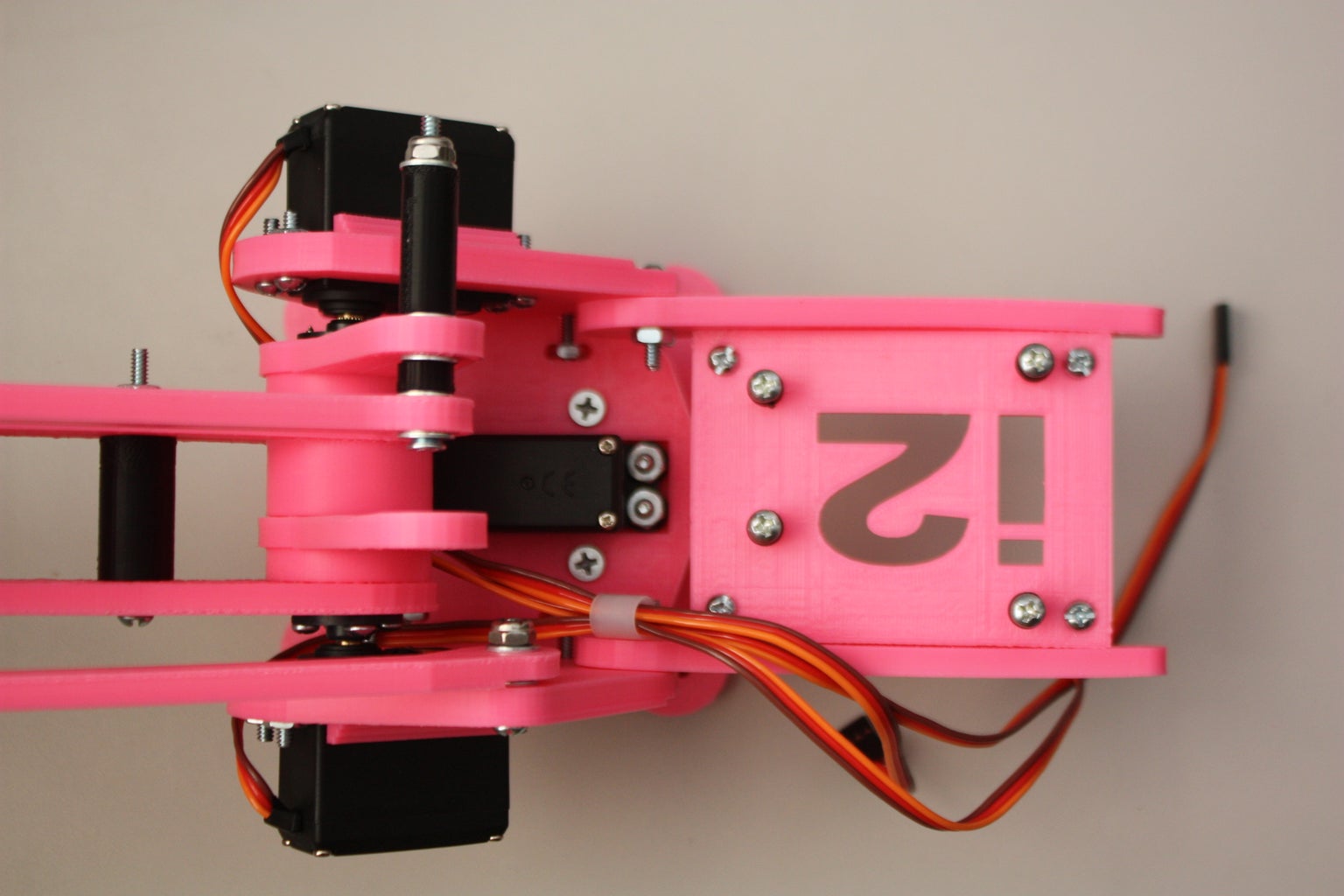
Step 16: Assembly: Step 15


- A length of threaded rod is used to tie the two shoulders together and tighten the entire arm chassis.
- Tighten this rod pulling the gaps (space) out of the parts between the two servo horns.
! Do NOT over tighten this bolt as servo damage will occur !
Step 17: Assembly: Step 16

Arduino mounting platform:
- This platform was designed for an Arduino Uno in mind, but an Arduino Duemilanove will fit just fine.
- Assemble as shown. Both supports will attach to corresponding holes in each of the shoulders. The platform mounts on top of the supports. Screw holes with risers are built into the platform to accommodate the Arduino.
Step 18: Finished Product!

Completed UArm Miniature Palletizing Robot Arm for Arduino
Step 19: Bonus Instructions


The two pictures above are condensed, easily printable pictograph instructions for uArm assembly.

Runner Up in the
Design Now: In Motion Contest

Participated in the
Robotics Contest 2017


