

Introduction: USB Freeform Arduino


This is a project in attempting to improve it predecessor "Freeform Arduino" by putting it in an enclosure and having it serve the similar purposes as "Palm Arduino Kit" and "Palm Arduino II" which I can carry it in my pocket and be available to use, and to connect to easy available power source specifically USB port.
.
I designed this "USB Freeform Arduino" with USB connector to be enclosed inside a 35mm film canister.
The biggest challenge is how I couid fasten the "none PCB Arduino" to it own enclosure, in this case cylinder shape canister?
The answer was not an easy one. But the solution I found was an easy thing to do, and it was an excellent solution that we quite familiar with.
"How about glue it in!", I said to myself.
Step 1: Parts and Tools


All the parts are about the same as used in it predecessor, "Freeform Arduino" except that I used film canister instead of the antistatic tube, with an addition USB type A connector.
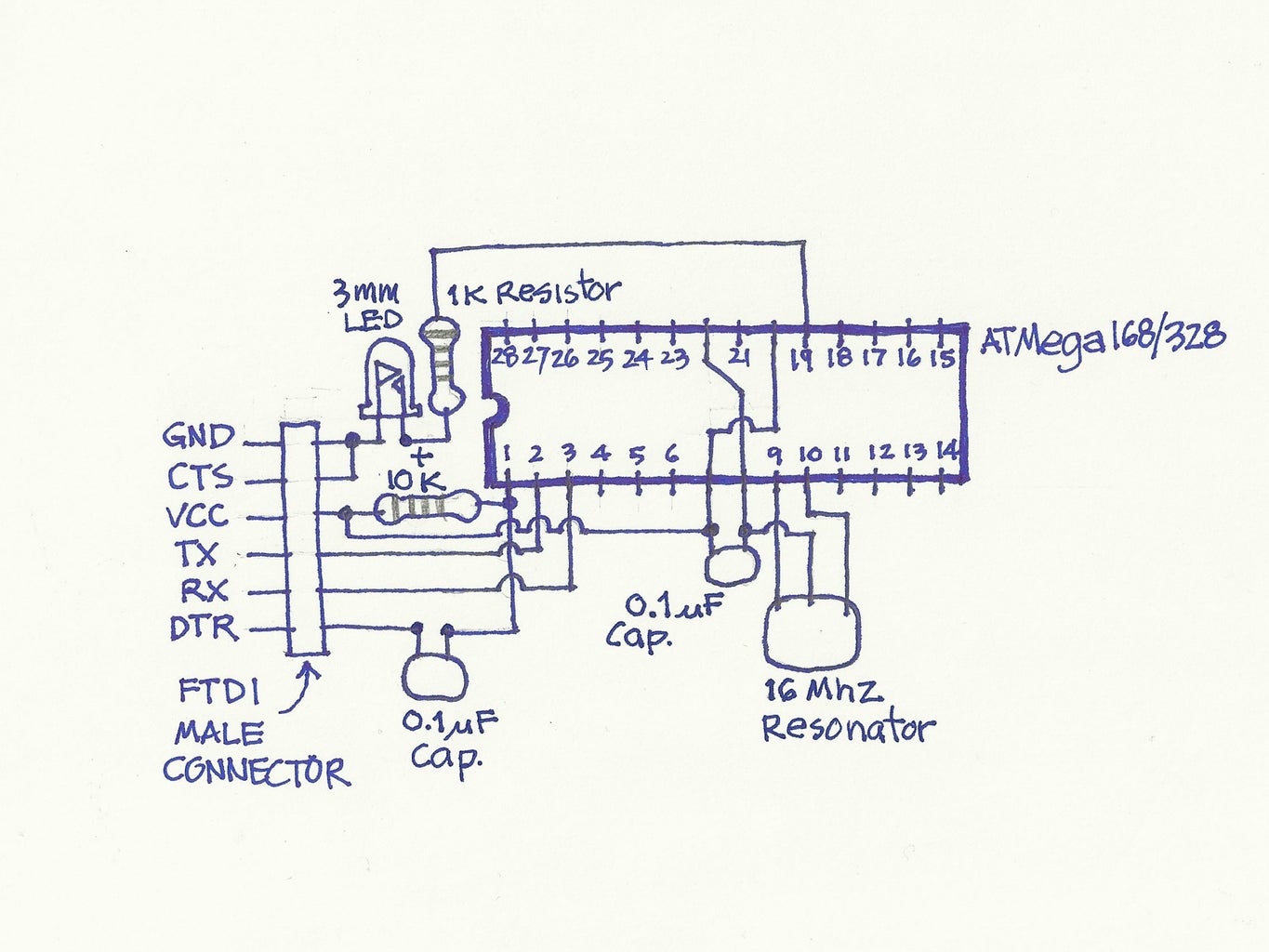
Schematic shown below is comprised of the minimum components and could be used FTDI cable to upload the sketch.
On the actual USB Freeform Arduino did not included the 1K resistor and 3mm LED that connected to pin D13 as in the schematic.
Parts
These are the minimum components to get Arduino up and running.
(1x) ATmega168/328 preloaded with Arduino Bootloader
(1x) 16 Mhz Resonator
(2x) 0.1uF Ceramic Capacitors (1x) 3mm red LED (Only needed for testing purpose only)(1x) 1K Resistor
(1x) 10K Resistor
(1x) 6-pin Male Header (as the connector to FTDI cable to upload the sketch)
(2x) 1x14 Female Receptacle
Additional Materials:
Hookup Wire
35mm Film Canister
USB Standard type A cable (Male Connector)
Tools
Solder iron and Solder station
Diagonal Cutter
Pliers
X-Acto Knife
Wire Stripper
SolderSucker
Miniature Files
Hand Drill
Micro drill bit for Hand drill
Masking tape
Super Glue
Step 2: Make Freeform Arduino


To make Freeform Arduino,
I started out by connecting the VCC and AVCC pins, pin number 7 (the actual pin number, not the Arduino's digital pin 7) and pin number 20 of ATmega168/328, together. And I also joined GND pins, pin number 8 and pin number 22 of ATmega168/328 together.
(See pins map here)
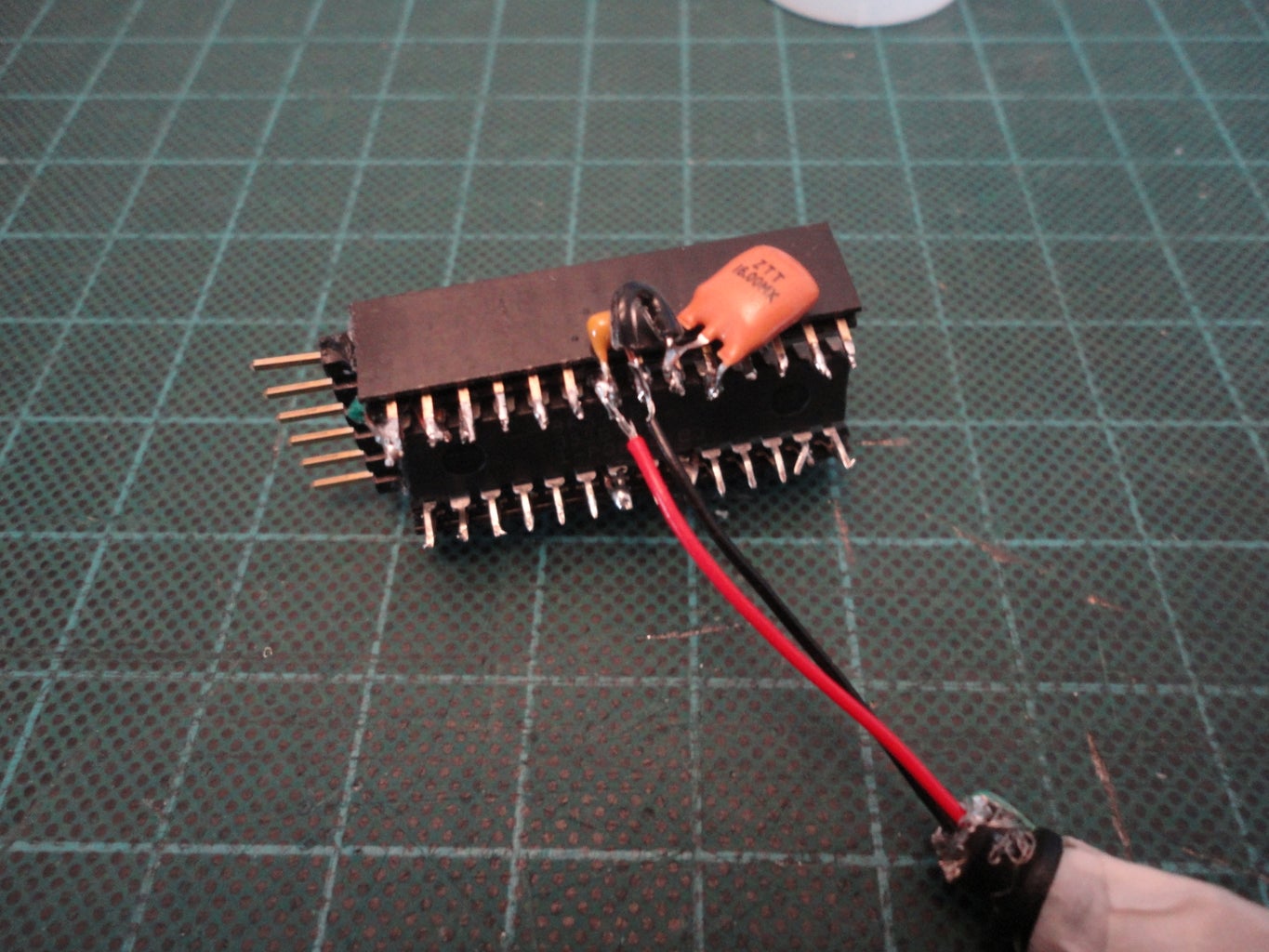
14-pin Female Receptacles
I soldered 14-pin receptacles to both sides of ATmega168/328 (with boot loader installed.) I set the angle of the 14-pin receptacles to lean a little bit outward to match the curvature of the canister cylinder shape.
0.1uF Capacitor
The capacitor does not have polarity. So I soldered left pin of the capacitor to ATmega168/328 pin number 7. And soldered the right pin of capacitor to ATmega168/328 pin number 8.
16kHz Resonator
The resonator has three pins, left and right are to be connected to XTAL1 and XTAL2 on ATmega168/328 (pin number 9 and 10). So, I soldered the right most pin of the resonator to pin number 10 (XTAL2), and used hookup wire to connect the left pin of resonator to pin number 9 of ATmega168/328. And used short hookup wire to join ground pin of resonator (middle pin) to ATmega168/328 pin number 8 (Ground).
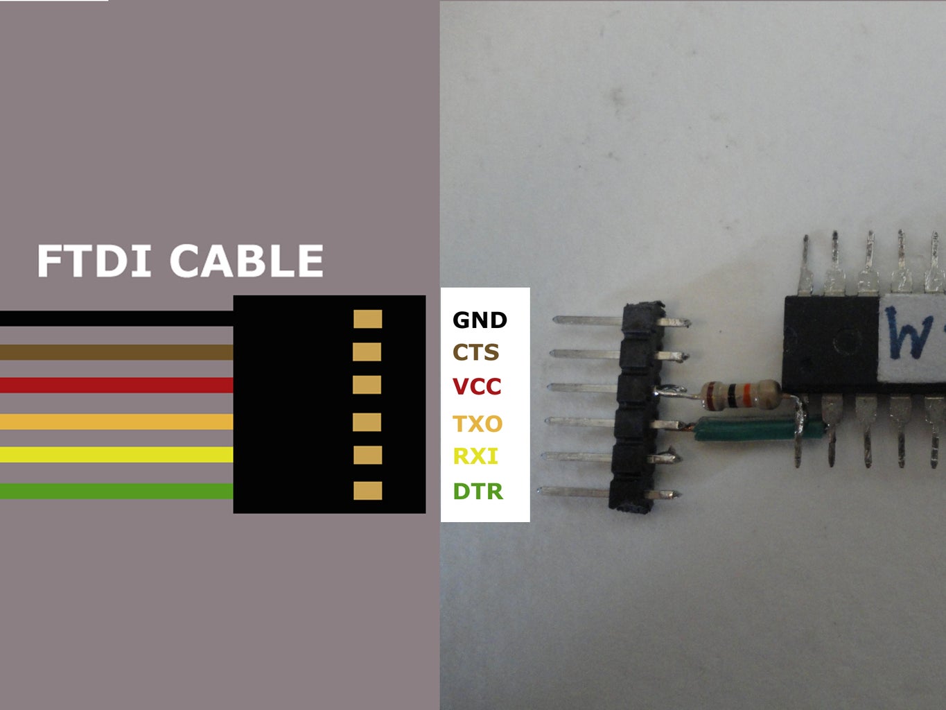
FTDI connector
I soldered six hookup wires to 6-pin Male header in this order (pointing the header out toward my right hand side).
And I soldered the hookup wires to ATmega168/328 as shown below.
ATmega168/328 Hookup wire FTDI pins
Ground Pin (8 or 22) Black GND
- - CTS (I connected this pin to GND pin above)
VCC Pin (7 or 20) Red VCC
RX Pin (2) White TX (out)
TX Pin (3) Green RX (in)
Reset Pin(1) Green DTR/RTS (I soldered 0.1uF ceramic capacitor between male header and hookup wire.)
After all the wires connected, I used SuperGlue to glue the FTDI header to the end of 14-pin receptacles over pin number 1 and 28 of ATmega168/328.
10K Resistor
I soldered 10K resistor in between VCC pin (pin number 7) and Reset pin (pin number 0) of ATmega168/328.
Note: For the details of how to make "Freeform Arduino" see the making steps of "Palm Arduino Kit", since it have the same schematics and it did not use PCB. There is no different in how to built steps between the First and this one, except Freeform Arduino does not have pin D13 LED and resistor.
Step 2: Straighten the pins (NOTE: Do not straighten the "USB Freeform Arduino")
Step 3: Added Power and Ground
Step 4: Bring out the pins (Note: You could bring out only digitals and analogs only and not omit the XTAL1, XTAL2, and GND pins - 8, 9, and 10 in this "USB Freeform Arduino" just like I did in "Palm Arduino II)
Now, we have Freeform Arduino ready for the next steps.
Step 3: The Enclosure - 35mm Film Canister


There is another kind of 35mm film canister, the one with the grey cap and black container. I avoided this one and used the white translucent canister instead, because I can see the shape of the object inside of it from the outside.
I was able to plot the position of the 14-pin receptacle of the ATmega168/328 to the surface of the canister. When I placed the Freeform Arduino close to the surface.
After I plotted the locations of the 14-pin receptacles with fine point Sharpie.
I used masking tape to shape the cut out areas on the canister.
Then I compared the dimension of the receptacles and the cut out area.
I used hand drill to drill the holes at the corners of the cut out.
And I used X-Acto knife to cut along the cutting lines from hole to hole.
(Be careful! The surface is slippery and it is not flat.)
After cut out all the opening I compared Freeform Arduino receptacles to the opening to see if the openings are OK.
Then I repeated the steps above to mark and cut the opening for the USB connector.
And I tried it out to see if the opening are OK.
Step 4: Test


As always I want to make sure everything is in working order before committing to the next steps.
So I temporarily soldered the VCC and GND wires of ATmega168/328 to USB cable.
I connected the FTDI cable to Freeform Arduino and upload the "Blinking LED" sketch to see if It would worked!
Then I unplugged the FTDI cable and inserted the Freeforn Arduino's USB power cable into USB ports.
The result, it was working as expected!
Step 5: Glue Them Up!


This step, I desoldered the USB's VCC and GND wires from the Freeform Arduino.
Then I added the hookup wires to VCC and GND pins of the Freeform Arduino.
I cleared the unused wires on the USB connector to be ready to be glued into the canister.
I used toothpick to paste the Super Glue to the canister and ATmega168/328 14-pin receptacles.
After the glue dried, I connected the VCC (pin 7) on ATmega168/328 to VCC on USB cable, and connected GND (pin 8) ATmega168/328 to GND Wire on USB cable together.
Next, I applied the Super Glue to the USB connector and canister with toothpick.
I tucked all the wiring inside the canister, and closed the lid.
And that's it! I got a "USB Freeform Arduino!"
(One more thing to do is to label all the pinouts.)
Step 6: The Final


Now coming to the final test I did uploaded the blinking LED sketch again, removed the FTDI cable, and then connected to the USB Port.
After I had done testing it on the PC. I connected the USB Freeform Arduino to Laptop USB port and it worked fine too!
I am very happy with the outcome of the project.
It looks really nice, and it really handy.
For the durability test, I dropped it a few times on the thin area rug. The glued parts did not split! And it's still working fine!
The mission is accomplished.
I'm hoping to use this in my future robot projects.
Since it is very compact. It could be hiding in the body of the robot.
Or if I were to use it in any other project it should be easy to fit it in any enclosure.
For the power cable, I could make a power cable with the USB Type A receptacle to supply the power to my "USB Freeform Arduino" since this version of "Freeform Arduino" already equipped with USB connector.
Thank you very much for your visit. I hope you enjoy reading it!
And hoping to see someone coming up with a better ideas! If so please share!

Finalist in the
3rd Annual Make It Stick Contest

Participated in the
Hack It! Contest

Participated in the
Make It Glow


