

Introduction: Universal Measure and Control System for SCIENCE Purposes


Hello.
This is my UNFINISHED science project. It NEWER BE FINISHED because i have no funds for finish it and my research facility have no funds to :(. This is politics of my country.
Introduction:
Idea was to buil universal research system for automatization research. In my university there are a lot of old soviet science equipment that work fine but it in"stone age". This project can connect to any equipment for "take experimental data".
Directly this project was constructed for my delatometry project. Universalization will/wass next step
Goals
1. Working temperature from -270Celsius till +1000Celsius
2. 3 points temperature mesuare (max supported 24bit 8 channels); 2 termocouple and high precision platinum termoresistor
3. Room temperature sensor lm35
4. 4 RS232 ports for connecting additional equipment.
4.1 in Delatometry used one RS232 for connectin RLC meter E720 (Belarusian device.... check photos)
5. High voltage 12 channels temperature control system
6.T ouchscreen for data-on-air displaying
7. All experimenal programs and experimental data was written to SDcard
8. Direct control via network. Ajax controlled via web interface
8.1 Idea was to control equipment via net in probably HAZARDOUS conditions
9. and other, and so on.... and many other ideas in small arduino mega
Time that i spend
1+ year of programming\constructin
Equipment
1. Arduino mega
2. ADS1256
3. Wizznet
4. Touchscreen+sdcart
5. Other equipment
What in this instructable
Step1. ADS1256. original PDF, Arduino shield DipTrace PDF, Arduino shield shematic, Part of working arduino code
Step 2 MNIPI E720 (мнипи е720)
Step 3. WIZZNET shield. Bug fixing!!!(many shields on store are china fake!!!. What bug and how to fix it)
Step 4. Ajax wia web browser. Control your equipment via browser
Step 5. Scetch
This instructable is as is. I hope that you'll get something helpfool. And be patient it was work of year of my life
If someone want - i can share delatometry tech.
Step 1: ADS1256 24 Bit, 30kSPS Very Low Noise Delta-Sigma ADC With Multiplexer
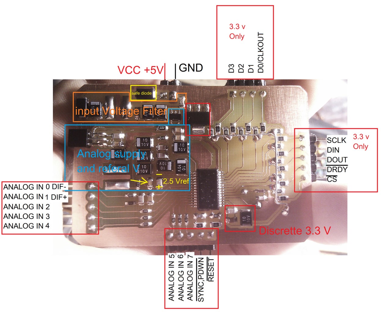
http://www.ti.com/product/ADS1256
On attached files datasheet, Shield datasheet, DipTrace
Part of code. All scetch code check on last step. This is working and tested piece of code
Firs of all youll need to "activate" this chip on boot
<p>#define LM35_pin A15</p><p>#define Spi_pin1 49 //ads1256 49
#define Spi_pin2 48 //sdcard
#define Spi_pin3 47
#define Spi_pin4 46
#define Spi_pin5 45
#define Spi_pin6 44
#define Spi_pin7 43
//#define Spi_pin8 42</p><p>#define Relay_pin3 41
#define Relay_pin2 40
#define Relay_pin1 39</p><p>#define ADS1256_irq 21</p><p>#define PWM_1 2
#define PWM_2 3
#define PWM_3 4
#define PWM_4 5
#define PWM_5 6
#define PWM_6 7
#define PWM_7 8
#define PWM_8 9
#define PWM_9 10
#define PWM_10 11</p><p>#define		STATUS    0x00 //Status Control Register 0
#define		MUX 	  0x01 //Multiplexer Control Register 0
#define		ADCON     0x02 //A/D Control Register 0
#define		DRATE	  0x03 //A/D Data Rate Control Register 0
#define		IO	      0X04 //GPIO Control Register 0
#define		OFC0	  0x05 //Offset Calibration Coefficient Register 1
#define		OFC1	  0x06 //Offset Calibration Coefficient Register 2
#define		OFC2	  0x07 //Offset Calibration Coefficient Register 2
#define		FSC0 	  0x08 //Full scale Callibration Coefficient Register 0
#define		FSC1	  0x09 //Full scale Callibration Coefficient Register 1
#define		FSC2	  0x0A //Full scale Callibration Coefficient REgister 2</p><p>/*STATUS - Status Control Register 0 ( see p30)*/
/* BIT7 - BIT6 -  BIT5   -  BIT4   -  BIT3   -  BIT2   -  BIT1   -  BIT0 */
/* ID   - ID   -  ID     -  ID     -  ORDER  -  ACAL   -  BUFEN  -  DRDY */
#define STATUS_RESET 0x01 // Reset STATUS Register
/*Bits 7 - 4 ID3, ID2, ID1, ID0 Factory Programmed Identification Bits(Read Only)*/
/*ORDER1:0  Data Output Bit Order*/
#define ORDER_MSB B00000000 // Most significant Bit first (default)
#define ORDER_LSB B00001000//Least significant Bit first
/*Input data is always shifted in most significant byte and bit first. Output data is always shifted out most significant
byte first. The ORDER bit only controls the bit order of the output data within the byte.*/
/*ACAL1:0 Auto Calibration*/
#define ACAL_OFF B00000000 // Auto Calibration Disabled (default)
#define ACAL_ON  B00000100 // Auto Calibration Enabled
/*When Auto-Calibration is enabled, self-calibration begins at the completion of the WREG command that changes
the PGA (bits 0-2 of ADCON register), DR (bits 7-0 in the DRATE register) or BUFEN (bit 1 in the STATUS register)
values.*/
/*BUFEN1:0 Analog Input Buffer Enable*/
#define BUFEN_OFF B00000000 //Buffer Disabled (default)
#define BUFEN_ON  B00000010 //BUffer Enabled
/*DRDY1:0 Data Ready (Read Only) Duplicates the state of the DRDY pin*</p><p>* MUX - Multiplexer Control Register 0 (see p31 - bring together with bitwise OR | */
/* BIT7  - BIT6  -  BIT5   -  BIT4   -  BIT3   -  BIT2   -  BIT1   -  BIT0 */
/* PSEL3 - PSEL2 -  PSEL1  -  PSEL0  -  NSEL3  -  NSEL2   - NSEL1   - NSEL0 */
#define MUX_RESET 0x01      // Reset MUX0 Register
/* PSEL3:0 Positive input channel selection bits */
#define P_AIN0 B00000000 //(default)
#define P_AIN1 B00010000
#define P_AIN2 B00100000
#define P_AIN3 B00110000
#define P_AIN4 B01000000
#define P_AIN5 B01010000
#define P_AIN6 B01100000
#define P_AIN7 B01110000
#define P_AINCOM B10000000
/* NSEL3:0 Negativ input channel selection bits */
#define N_AIN0 B00000000
#define N_AIN1 B00000001 //(default)
#define N_AIN2 B00000010
#define N_AIN3 B00000011
#define N_AIN4 B00000100
#define N_AIN5 B00000101
#define N_AIN6 B00000110
#define N_AIN7 B00000111
#define N_AINCOM B00001000</p><p>/*ADCON - A/D Control Register 0 ( see p31)*/
/* BIT7 - BIT6   -  BIT5   -  BIT4   -  BIT3   -  BIT2   -  BIT1   -  BIT0 */
/* 0    - CLK1   -  CLK0   -  SDCS1  -  SDCS0  -  PGA2   -  PGA1   -  PAG0 */
#define ADCON_RESET 0x20 // Reset ADCON Register
/*CLK2:0 D0/CLKOUT Clock Out Rate Setting*/
#define CLK_OFF B00000000 //Clock Out off
#define CLK_1   B00100000 //Clock Out Frequency = fCLKIN (default)
#define CLK_2   B01000000 //Clock Out Frequency = fCLKIN/2
#define CLK_4   B01100000 //Clock Out Frequency = fCLKIN/4
/*When not using CLKOUT, it is recommended that it be turned off. These bits can only be reset using the RESET pin.*/
/*SDCS2:0 Sensor Detection Current Sources*/
#define SDCS_OFF B00000000//Sensor Detect Off (default)
#define SDCS_05  B00001000//Sensor Detect Current 0.5?A
#define SDCS_2   B00010000//Sensor Detect Current 2?A
#define SDCS_10  B00011000//Sensor Detect Current 10?A
/*The Sensor Detect Current Sources can be activated to verify the integrity of an external sensor supplying a signal to the
ADS1255/6. A shorted sensor produces a very small signal while an open-circuit sensor produces a very large signal.*/
/*PGA3:0 Programmable Gain Amplifier Setting*/
#define PGA_1  B0//(default)
#define PGA_2 B1
#define PGA_4 B10
#define PGA_8 B11
#define PGA_16 B100
#define PGA_32 B101
#define PGA_64 B110</p><p>/*DRATE - A/D Data Rate Register 0 ( see p32)*/
/* BIT7 - BIT6   -  BIT5   -  BIT4   -  BIT3   -  BIT2   -  BIT1   -  BIT0 */
/* DR7  - DR6    -  DR5    -  DR4    -  DR3    -  DR2    -  DR1    -  DR0 */
#define DRATE_RESET 0xF0 // Reset DRATE Register
/*DR7:0 Data Rate Setting*/
#define DR_30000 B11110000 //30.000 SPS (default)
#define DR_15000 B11100000 //15.000 SPS
#define DR_7500  B11010000 //7.500 SPS
#define DR_3750  B11000000 //3.750 SPS
#define DR_2000  B10110000 //2.000 SPS
#define DR_1000  B10100001 //1.000 SPS
#define DR_500   B10010010 //500 SPS
#define DR_100   B10000010 //100 SPS
#define DR_60    B01110010 //60 SPS
#define DR_50    B01100011 //50 SPS
#define DR_30    B01010011 //30 SPS
#define DR_25    B01000011 //25 SPS
#define DR_15    B00110011 //15 SPS
#define DR_10    B00100011 //10 SPS
#define DR_5     B00010011 //5 SPS
#define DR2_5    B00000011 //2,5 SPS</p><p>/*IO - GPIO Control Register 0 ( see p32)*/
/* BIT7 - BIT6   -  BIT5   -  BIT4   -  BIT3   -  BIT2   -  BIT1   -  BIT0 */
/* DIR3 - DIR2   -  DIR1   -  DIR0   -  DIO3   -  DIO2   -  DIO1   -  DIO0 */
#define IO_RESET 0xE0 // Reset IO Register
/*DIR3 - Digital I/O Direction for Pin D3*/
#define DIR3_OUT B00000000 //D3 is an output
#define DIR_IN   B10000000 //D3 is an input (default)
/*DIR2 - Digital I/O Direction for Pin D3*/
#define DIR2_OUT B00000000 //D2 is an output
#define DIR2_IN   B01000000 //D2 is an input (default)
/*DIR1 - Digital I/O Direction for Pin D3*/
#define DIR1_OUT B00000000 //D1 is an output
#define DIR1_IN   B001ЯЯ000 //D1 is an input (default)
/*DIR0 - Digital I/O Direction for Pin D3*/
#define DIR0_OUT B00000000 //D0/CLKOUT is an output
#define DIR0_IN   B00010000 //D0/CLKOUT is an input (default)
/*DIO3:0 Status of Digital I/O, Read Only*</p><p>* SPI COMMAND DEFINITIONS (p34) */
/*SYSTEM CONTROL */
#define		WAKEUP		0x00 	//Exit Sleep Mode
#define 	STANDBY		0xFD	//Enter Sleep Mode
#define 	SYNC 		0xFC    //Synchornize the A/D Conversion
#define 	RESET		0xFE	//Reset To Power UP values
#define		NOP			0xFF	//No operation
/*DATA READ*/
#define		RDATA		0x01	//Read data once
#define 	RDATAC		0x03	//Read data continously
#define 	SDATAC 		0x0F	//Stop reading data continously
/*READ REGISTER */
#define 	RREG		0x10	//Read From Register
#define 	WREG 		0x50	//Write To Register
/*Calibration */
#define 	SYSOCAL		0xF3	//System Offset Calibration
#define 	SYSGCAL		0xF2	//System Gain Calibration
#define 	SELFCAL	    0xF0	//Self Offset Calibration</p><p>#define SPI_SPEED SPI_CLOCK_DIV4//1700000
volatile int DRDY_state = HIGH;</p><p>#include <SPI.h></p><p>void setup() {</p><p>
DDRL=B11111111;
PORTL=B11111111;
pinMode(53, OUTPUT);
digitalWrite(53, LOW); </p><p>


SPI.begin();
SD.begin();
Serial.begin(9600);</p><p>Read_default_config();	</p><p>ads1256_config(); </p><p>}

</p><p>uint8_t ADS1256_ReadChipID(void)<br>{
  uint8_t id;</p><p> // waitforDRDY();
  id = ADS1256_ReadReg(STATUS);
  return (id);// >> 4);
}</p><p>static uint8_t ADS1256_ReadReg(uint8_t _RegID)
{
  byte id = GetRegisterValue(STATUS);
  return id>>4; //3 ok
}</p><p>void loop() {<br>exp_run=1;  </p><p>volt_val=ads1256_GetConversion();</p><p>}</p><p>//++++++++++++++++++++++++++++++++++++++++++++++++++++++++++++++++++++==<br>//++++++++++++++++++++++++++==ads1256===================================</p><p>void ads1256_config()</p><p>{
attachInterrupt(digitalPinToInterrupt(ADS1256_irq), DRDY_Interuppt, FALLING); //Interrupt setup for DRDY detection
ads1256_Reset();</p><p>//SetRegisterValue(STATUS, ACAL_ON);
//SetRegisterValue(STATUS, );
//SetRegisterValue(SELFCAL, ACAL_ON);
//SetRegisterValue(MUX, MUX_SP2_AIN0 | MUX_SN2_AIN1);
//	SetRegisterValue(MUX, REFSELT1_ON | VREFCON1_ON);	  //ADS Reference on Intern, Internal Reference on
//	SetRegisterValue(VBIAS, VBIAS_0);
//SetRegisterValue(DRATE, DR_5);		   // 2000 sps vollkommen unьtz rauschen ьberwiegt
//SetRegisterValue(ADCON, B00000111);
//SetRegisterValue(MUX, P_AIN0 | N_AINCOM);
//SetRegisterValue(DRATE, DR_5);
//SendCMD(WAKEUP);</p><p>//    ADS1256_Send8Bit(CMD_WREG | 0);  /* Write command register, send the register address */
//    ADS1256_Send8Bit(0x03);      /* Register number 4,Initialize the number  -1*</p><p>/    ADS1256_Send8Bit(buf[0]);  /* Set the status register */
//    ADS1256_Send8Bit(buf[1]);  /* Set the input channel parameters */
//    ADS1256_Send8Bit(buf[2]);  /* Set the ADCON control register,gain */
//    ADS1256_Send8Bit(buf[3]);  /* Set the output rate */
uint8_t buf[4];
 buf[0] = ads_conf[0];//(0 << 3) | (1 << 2) | (0 << 1);  // The internal buffer is prohibited
 buf[1] = ads_conf[1];//0x08;
 buf[2] = B110;//ads_conf[2];//(0 << 5) | (0 << 3) | (0 << 0);
 buf[3]=DR_1000;//ads_conf[3];//DR_5;
SPI.beginTransaction(SPISettings(SPI_SPEED, MSBFIRST, SPI_MODE1)); // initialize SPI with  clock, MSB first, SPI Mode1
	digitalWrite(Spi_pin1, LOW);
	delayMicroseconds(10);
        SPI.transfer(WREG | 0); // send 1st command byte, address of the register
        SPI.transfer(0x03);
	SPI.transfer(buf[0]); //Reset
        SPI.transfer(buf[1]); //Reset
        SPI.transfer(buf[2]); //Reset
        SPI.transfer(buf[3]); //Reset
	digitalWrite(Spi_pin1, HIGH);
	SPI.endTransaction();
delayMicroseconds(50);
}</p><p>void ads1256_Reset() {
	SPI.beginTransaction(SPISettings(SPI_SPEED, MSBFIRST, SPI_MODE1)); // initialize SPI with  clock, MSB first, SPI Mode1
	digitalWrite(Spi_pin1, LOW);
	delayMicroseconds(10);
	SPI.transfer(RESET); //Reset
	delay(2); //Minimum 0.6ms required for Reset to finish.
	SPI.transfer(SDATAC); //Issue SDATAC
	delayMicroseconds(100);
	digitalWrite(Spi_pin1, HIGH);
	SPI.endTransaction();
}</p><p>void SetRegisterValue(uint8_t regAdress, uint8_t regValue) {
	uint8_t regValuePre = GetRegisterValue(regAdress);
	if (regValue != regValuePre) {
		//digitalWrite(13, HIGH);
		delayMicroseconds(10);
		waitforDRDY();
		SPI.beginTransaction(SPISettings(SPI_SPEED, MSBFIRST, SPI_MODE1)); // initialize SPI with SPI_SPEED, MSB first, SPI Mode1
		digitalWrite(Spi_pin1, LOW);
		delayMicroseconds(10);
		SPI.transfer(WREG | regAdress); // send 1st command byte, address of the register
		SPI.transfer(0x00);		// send 2nd command byte, write only one register
		SPI.transfer(regValue);         // write data (1 Byte) for the register
		delayMicroseconds(10);
		digitalWrite(Spi_pin1, HIGH);
		//digitalWrite(13, LOW);
		if (regValue != GetRegisterValue(regAdress)) {   //Check if write was succesfull
			Serial.print("Write to Register 0x");
			Serial.print(regAdress, HEX);
			Serial.println(" failed!");
		}
		SPI.endTransaction();

	}</p><p>}</p><p>//function to read a register value from the adc
//argument: adress for the register to read
unsigned long GetRegisterValue(uint8_t regAdress) {
	//digitalWrite(13, HIGH);
	waitforDRDY();
	SPI.beginTransaction(SPISettings(SPI_SPEED, MSBFIRST, SPI_MODE1)); // initialize SPI with 4Mhz clock, MSB first, SPI Mode0
	uint8_t bufr;
	digitalWrite(Spi_pin1, LOW);
	delayMicroseconds(10);
	SPI.transfer(RREG | regAdress); // send 1st command byte, address of the register
	SPI.transfer(0x00);			// send 2nd command byte, read only one register
	delayMicroseconds(10);
	bufr = SPI.transfer(NOP);	// read data of the register
	delayMicroseconds(10);
	digitalWrite(Spi_pin1, HIGH);
	//digitalWrite(13, LOW);
	SPI.endTransaction();
	return bufr;
}</p><p>static uint8_t ADS1256_Recive8Bit(void)
{
  uint8_t read = 0;
  read = SPI.transfer(0xff);
  return read;
}</p><p>long ads1256_GetConversion() {
	int32_t regData;
        static uint8_t buf[3];
digitalWrite(Spi_pin1, LOW);
	waitforDRDY(); // Wait until DRDY is LOW
      //  SetRegisterValue(MUX,conf);
	SPI.beginTransaction(SPISettings(SPI_SPEED, MSBFIRST, SPI_MODE1));
	delayMicroseconds(25); // RD: Wait 25ns for ADC12xx to get ready
                SPI.transfer(WREG | MUX); // send 1st command byte, address of the register
		SPI.transfer(0x00);		// send 2nd command byte, write only one register
		SPI.transfer(B00110010);         // write data (1 Byte) for the register
SPI.transfer(SYNC);
    delayMicroseconds(5);</p><p>    SPI.transfer(WAKEUP);</p><p>	 //Pull SS Low to Enable Communications with ADS1247
	delayMicroseconds(25); // RD: Wait 25ns for ADC12xx to get ready
        SPI.transfer(RDATA); //Issue RDATA
        delayMicroseconds(5);
    buf[0] = ADS1256_Recive8Bit();delayMicroseconds(5);
    buf[1] = ADS1256_Recive8Bit();delayMicroseconds(5);
    buf[2] = ADS1256_Recive8Bit();</p><p>    regData = (buf[0] << 16) & 0x00FF0000;
    regData |= (buf[1] << 8);  /* Pay attention to It is wrong   read |= (buf[1] << 8) */
    regData |= buf[2];</p><p>	//delayMicroseconds(10);

	SPI.endTransaction();
digitalWrite(Spi_pin1, HIGH);
Serial.print(buf[0],HEX);Serial.print(buf[1],HEX);Serial.println(buf[2],HEX);
delay(200);
  if (regData & 0x800000)
   {
      regData |= 0xFF000000;
    }
	return regData;
}</p><p>void SendCMD(uint8_t cmd) {
	waitforDRDY();
	SPI.beginTransaction(SPISettings(SPI_SPEED, MSBFIRST, SPI_MODE1)); // initialize SPI with 4Mhz clock, MSB first, SPI Mode0
	digitalWrite(Spi_pin1, LOW);
	delayMicroseconds(10);
	SPI.transfer(cmd);
	delayMicroseconds(10);
	digitalWrite(Spi_pin1, HIGH);
	SPI.endTransaction();
}</p><p>void waitforDRDY() {
	while (DRDY_state) {
		continue;
	}
	noInterrupts();
	DRDY_state = HIGH;
	interrupts();
}</p><p>//Interrupt function
void DRDY_Interuppt() {
	DRDY_state = LOW;
}</p><p>void ADS1256_ISR(void)
{
  if (g_tADS1256.ScanMode == 0)  /*  0  Single-ended input  8 channel?¬ 1 Differential input  4 channe */
  {</p><p>    ADS1256_SetChannal(g_tADS1256.Channel);  /*Switch channel mode */
    delayMicroseconds(5);</p><p>    SendCMD(SYNC);
    delayMicroseconds(5);</p><p>    SendCMD(WAKEUP);
    delayMicroseconds(25);</p><p>    if (g_tADS1256.Channel == 0)
    {
      g_tADS1256.AdcNow[7] = ads1256_GetConversion();
    }
    else
    {
      g_tADS1256.AdcNow[g_tADS1256.Channel-1] = ads1256_GetConversion();
    }</p><p>    if (++g_tADS1256.Channel >= 8)
    {
      g_tADS1256.Channel = 0;
    }
  }
  else  /*DiffChannal*/
  {

    ADS1256_SetDiffChannal(g_tADS1256.Channel);  /* change DiffChannal */
    delayMicroseconds(5);</p><p>    SendCMD(SYNC);
    delayMicroseconds(5);</p><p>    SendCMD(WAKEUP);
    delayMicroseconds(25);</p><p>    if (g_tADS1256.Channel == 0)
    {
      g_tADS1256.AdcNow[3] = ads1256_GetConversion();
    }
    else
    {
      g_tADS1256.AdcNow[g_tADS1256.Channel-1] =ads1256_GetConversion();
    }</p><p>    if (++g_tADS1256.Channel >= 4)
    {
      g_tADS1256.Channel = 0;
    }
  }
}</p><p>static void ADS1256_SetChannal(uint8_t _ch)
{
  /*
  Bits 7-4 PSEL3, PSEL2, PSEL1, PSEL0: Positive Input Channel (AINP) Select
    0000 = AIN0 (default)
    0001 = AIN1
    0010 = AIN2 (ADS1256 only)
    0011 = AIN3 (ADS1256 only)
    0100 = AIN4 (ADS1256 only)
    0101 = AIN5 (ADS1256 only)
    0110 = AIN6 (ADS1256 only)
    0111 = AIN7 (ADS1256 only)
    1xxx = AINCOM (when PSEL3 = 1, PSEL2, PSEL1, PSEL0 are ?°don??t care?±)</p><p>    NOTE: When using an ADS1255 make sure to only select the available inputs.</p><p>  Bits 3-0 NSEL3, NSEL2, NSEL1, NSEL0: Negative Input Channel (AINN)Select
    0000 = AIN0
    0001 = AIN1 (default)
    0010 = AIN2 (ADS1256 only)
    0011 = AIN3 (ADS1256 only)
    0100 = AIN4 (ADS1256 only)
    0101 = AIN5 (ADS1256 only)
    0110 = AIN6 (ADS1256 only)
    0111 = AIN7 (ADS1256 only)
    1xxx = AINCOM (when NSEL3 = 1, NSEL2, NSEL1, NSEL0 are ?°don??t care?±)
  */
  if (_ch > 7)
  {
    return;
  }
  SetRegisterValue(MUX, (_ch << 4) | (1 << 3));  /* Bit3 = 1, AINN connection AINCOM */
}</p><p>static void ADS1256_SetDiffChannal(uint8_t _ch)
{
  /*
  Bits 7-4 PSEL3, PSEL2, PSEL1, PSEL0: Positive Input Channel (AINP) Select
    0000 = AIN0 (default)
    0001 = AIN1
    0010 = AIN2 (ADS1256 only)
    0011 = AIN3 (ADS1256 only)
    0100 = AIN4 (ADS1256 only)
    0101 = AIN5 (ADS1256 only)
    0110 = AIN6 (ADS1256 only)
    0111 = AIN7 (ADS1256 only)
    1xxx = AINCOM (when PSEL3 = 1, PSEL2, PSEL1, PSEL0 are ?°don??t care?±)</p><p>    NOTE: When using an ADS1255 make sure to only select the available inputs.</p><p>  Bits 3-0 NSEL3, NSEL2, NSEL1, NSEL0: Negative Input Channel (AINN)Select
    0000 = AIN0
    0001 = AIN1 (default)
    0010 = AIN2 (ADS1256 only)
    0011 = AIN3 (ADS1256 only)
    0100 = AIN4 (ADS1256 only)
    0101 = AIN5 (ADS1256 only)
    0110 = AIN6 (ADS1256 only)
    0111 = AIN7 (ADS1256 only)
    1xxx = AINCOM (when NSEL3 = 1, NSEL2, NSEL1, NSEL0 are ?°don??t care?±)
  */
  if (_ch == 0)
  {
    SetRegisterValue(MUX, (0 << 4) | 1);  /* DiffChannal  AIN0?¬ AIN1 */
  }
  else if (_ch == 1)
  {
    SetRegisterValue(MUX, (2 << 4) | 3);  /*DiffChannal   AIN2?¬ AIN3 */
  }
  else if (_ch == 2)
  {
    SetRegisterValue(MUX, (4 << 4) | 5);  /*DiffChannal    AIN4?¬ AIN5 */
  }
  else if (_ch == 3)
  {
    SetRegisterValue(MUX, (6 << 4) | 7);  /*DiffChannal   AIN6?¬ AIN7 */
  }
}</p>
Step 2: MNIPI E720 (мнипи Е720)

full class for work with this device using arduino Serial2. Add this before setup
<p>//====================================================================e720<br>String inputString = "";         // a string to hold incoming data
boolean stringComplete2 = false;  // whether the string is complete
boolean stringComplete = false;
         char* imparam;
         char* secparam;
         double firstvalue;
         double secondvalue;
         double param[8];
class e720
{
  public:
    e720();
    int OffSet();
    int Level();
    int Freq();
    int Freq10();
  //  void dot();
 //   void dash();
  //private:
    String input_string;
    double Limit();
    int ImParam();
    int SecParam();
    long SecondValue();
    long FirstValue();
    int OnChange();
    char* decode(int i);
   // private:
    int SecValue10();
  //  int Secvalue();
    int ImValue10();
   // int ImValue();
};</p><p>e720::e720()
{
input_string.reserve(22);
}</p><p>int e720::OffSet()//string 3,2
{
int temp=input_string[2]*256;
if (input_string[1]>=0) temp=temp+input_string[1]; else temp=temp+256+input_string[1];
return temp;
}</p><p>int e720::Level()//string 4
{
return input_string[3];
}</p><p>int e720::Freq()//string 6,5
{
int temp=input_string[5]*256+input_string[4];
if (input_string[5]>128) temp=temp-65535;
return temp;
}</p><p>int e720::Freq10()//string 7
{

  int temp=input_string[6];
   if (input_string[6]>128) temp=temp-65535;
   if (temp<0) temp=1;
   return temp;</p><p>}
double e720::Limit()//string 10//return Ohm
{
  byte temp=input_string[9];
 // Serial.println(temp,DEC);
  //if (input_string[9]>128) temp=temp-65535;
//  Serial.println(temp,DEC);
  switch (temp){
  case 1:return 10000000; break;
  case 2:return 1000000; break;
  case 3:return 100000; break;
  case 4:return 10000; break;
  case 5:return 1000; break;
  case 6:return 100; break;
  case 7:return 10; break;
  case 8:return 1; break;
  }
  </p><p>}</p><p>int e720::ImParam()//string 11
{

  int temp=input_string[10];
  if (input_string[10]>128) temp=temp-65535;
  return temp;</p><p>}
int e720::SecParam()//string 12
{

  int temp=input_string[11];
  if (input_string[11]>128) temp=temp-65535;
  return temp;</p><p>}</p><p>long e720::SecondValue()//string 15-14-13 16
{

  uint32_t Secvalue=input_string[14]*256*256+input_string[13]*256+input_string[12];
  if (input_string[14]>128) Secvalue=Secvalue-65535;</p><p>  //int SecValue10=input_string[15];
 // if (input_string[15]>128) SecValue10=SecValue10-256;
//  uint32_t temp=Secvalue*pow(10,SecValue10);
  if (Secvalue>=100000) return 0; else return Secvalue;
}</p><p>long e720::FirstValue()//string 16
{

     uint32_t ImValue=input_string[18]*256*256+input_string[17]*256+input_string[16];
     if (input_string[18]>128) ImValue=ImValue-65535; </p><p>if (ImValue>=100000) return 0; else return ImValue;

/*
  int ImValue=input_string[18]*256*256+input_string[17]*256+input_string[16];
  if (input_string[18]>128) ImValue=ImValue-65535;
  int ImValue10=input_string[19];
  if (input_string[19]>128) ImValue10=ImValue10-256;
 return ImValue*pow(10,ImValue10);
 */
}</p><p>int e720::ImValue10()
{
int temp=input_string[19];
if (input_string[19]>128) temp=temp-256;
if (temp<-20) return 0; else return temp;
}</p><p>int e720::SecValue10()
{
  int temp=input_string[15];
  if (input_string[15]>128) temp=temp-256;
if (temp<-20) return 0; else return temp;
}
int e720::OnChange()//string 21
{

  int temp=input_string[20];
  if (input_string[20]>128) temp=temp-65535;
  return temp;</p><p>}</p><p>char* e720::decode(int i)// /secparam/imparam
{
  switch (i) {</p><p>  case 0: return "Cp";break;
  case 1: return "Lp";break;
  case   2: return "Rp";break;
  case   3: return "Gp";break;
  case   4: return "Bp";break;
  case   5: return "|Y|";break;
  case   6: return "Q";break;
  case   7: return "Cs";break;
  case   8: return "Ls";break;
  case   9: return "Rs";break;
  case   10: return "Phi";break;
  case   11: return "Xs";break;
  case   12: return "|Z|";break;
  case   13: return "D";break;
  case   14: return "I";break;
  default : return "Cp";break;
  }
}</p><p>e720 test;</p><p>void serialEvent2() {
  while (Serial2.available()) {
    // get the new byte:
    char inChar = (char)Serial2.read();
    // add it to the inputString:
    test.input_string += inChar;
    // if the incoming character is a newline, set a flag
    // so the main loop can do something about it:
   // if (inChar == '\n') {
     if (test.input_string.length()>=22) {
      stringComplete2 = true;
    }
  }
}</p><p>void setup()</p><p>{</p><p>Serial2.begin(9600); //e720 port</p><p>}

void loop()</p><p>{</p><p>if (stringComplete2) {<br>
                      imparam=test.decode(test.ImParam());
                      firstvalue=test.FirstValue();
                      secparam=test.decode(test.SecParam());
                      secondvalue=test.SecondValue();
                      param[0]=test.Freq();
                      param[7]=test.Freq10();
                      param[1]=test.OnChange();
                      param[2]=test.OffSet();
                      param[3]=test.Level();
                      param[4]=test.Limit();
                      param[5]=test.ImValue10();
                      param[6]=test.SecValue10();


    test.input_string = "";
    stringComplete2 = false;
   }</p><p>

}</p>
Step 3: Wizznet Bug and Fixing


https://www.arduino.cc/en/Main/ArduinoEthernetShie...
Bug that i found - problem with link up\down. Long time ethernet link up\down. Collision on link. Some time you'll need reboot board.
China make mistake on assembly(check place of bag on first photo). After RJ45 on datasheet is installed 50ohm resistor. China make mistake and install 50Kohm resistor
In attached photos how i fix this using what i have.
Step 4: Arduino and Ajax
1. add to your sd card html files
2. make your own logic
html
1. Page automaticly read data from arduino once in 2 seconds
2. On page 16 buttons, that can be clicked by user. After click arduino immideatelly execute comand
i use directly manipulation. Yes i know abaut jquery and other.... My function need minimal memory on arduino
Attached zip file - data that stored on sd card. When you connect to ex:http://192.168.1.200 you'll get index.htm, other.html .... and all files that your browser request
on arduino side
<p>#define Spi_pin2 48 //sdcard
<pre>
#include <SPI.h>
#include <SD.h>
#include <EEPROM.h> //i store all config on eeprom. experimental program on eeprom too
#include <Ethernet.h>

#include <UTFT.h>
#include <UTouch.h>

#include <MemoryFree.h> //this library show free ram and clean unused ram

<p>EthernetServer server(80);</p><p>File webFile;                    // handle to files on SD card
String HTTP_req; // buffered HTTP request stored as null terminated string
byte Net[4][4];
EthernetClient client ;  // try to get client

void Net_config()
{
  uint8_t mac[6] = {0x00,0x01,0x02,0x03,0x04,0x05};
  IPAddress ip(Net[0][0],Net[0][1],Net[0][2],Net[0][3]);
  IPAddress gateway(Net[1][0], Net[1][1], Net[1][2], Net[1][3]);
  IPAddress subnet(Net[2][0], Net[2][1], Net[2][2], Net[2][3]);
  Ethernet.begin(mac, ip, gateway, subnet);
  server.begin();
}</p><p>void enable_device(int number) //i use this function to switch different SPI devices. My board support 8 addon cards
{
  SPI.endTransaction();delayMicroseconds(5);
  digitalWrite(53, HIGH);
  PORTL=B11111111;
  digitalWrite(number, LOW);//delay(1);
}</p>
<p>void setup() {<br>DDRL=B11111111; //check man page direct port manipulation
PORTL=B11111111;
pinMode(53, OUTPUT); //for wizznet library work
digitalWrite(53, LOW);  //i fix library and now it support any spi pin</p><p>SPI.begin();
pinMode(48, OUTPUT); //sdcard
digitalWrite(48, HIGH);
SD.begin(48);</p><p>
Read_default_config();	//read eeprom
Net_config(); //read network from eeprom

HTTP_req.reserve(100);
inputString.reserve(2);</p><p> pinMode(13, OUTPUT);</p><p>}</p><p>void loop() {<br> </p><p>request_parser();

}</p>
<p>void request_parser()<br>{

  EthernetClient client = server.available();  // try to get client

    if (client) {  // got client?
        boolean currentLineIsBlank = true;
        boolean fierstchar=false;
      while(client.connected()){
        if  (client.available()) {   // client data available to read
                char c = client.read(); // read 1 byte (character) from client


                if (c=='G' && fierstchar==false)   {fierstchar=true;}
                if  (fierstchar)    HTTP_req += c;
                if (c == '\n' && fierstchar==true) {
                    // send a standard http response header

                    parse_ajax(client);
                    // AJAX request for switch state

                    Serial.print(HTTP_req);
                    fierstchar=false;
                    HTTP_req = "";            // finished with request, empty string
                    break;
                } //client.stop();
                // every line of text received from the client ends with \r\n


            }
        }
        delay(1);      // give the web browser time to receive the data
    //client.flush();
    client.stop(); // close the connection
    }
 //client.stop();
}</p><p>void Return_Headers(EthernetClient cl,int header)
{  //enable_device(53);
  cl.println("HTTP/1.1 200 OK");
  switch (header){
  case 1: cl.println("Content-Type: text/xml"); break;
  default: cl.println("Content-Type: text/html");
  }
  cl.println("Connection: keep-alive");
  cl.println();
//  cl.flush();
}</p><p>void GetSwitchState(EthernetClient cl)
{
enable_device(53);
 cl.write("data test");
}</p><p>void Return_file(EthernetClient cl,char* file)
{
 enable_device(Spi_pin2);
 if (!SD.exists(file)) {
        Serial.println("ERROR 404 - Can't find file!");
        cl.println("ERROR 404 - Can't find file!");

    } else{
         webFile= SD.open(file,O_READ);
         if (webFile.isDirectory()) {
          //enable_device(53);
          cl.println("
</p><h3>Lift of files in directory</h3><p><br>");
             while (true)
               {
                File entry =  webFile.openNextFile();
                if (! entry)    {break;}
                char* temp=entry.name();
                if (entry.isDirectory()) {////enable_device(53);
              cl.println("/");
            //enable_device(Spi_pin2);
          }
               // //enable_device(53);
                cl.print("<a href="\"");cl.print(file);cl.print("/");cl.print(temp);cl.print("\"">");cl.print(temp);cl.print("</a><br>");
                }
 //enable_device(Spi_pin2);
 webFile.close();
 }
 else
 if (webFile) {       // enable_device(Spi_pin2);

                       while(webFile.available()) {
                       //enable_device(53);
                       // send web page to client
                       cl.write(webFile.read());
                        }

                        //enable_device(Spi_pin2);
                        webFile.close();
                    }
                  }

  enable_device(53);
  //cl.println(millis());</p><p>}</p><p>void parse_ajax(EthernetClient cl)
{
  int temp_test=0;
for (int i=0;i<=25;i++) {
//  Serial.print(HTTP_req.indexOf(Ajax_database(i)));Serial.println(i);
if (HTTP_req.indexOf(Ajax_database(i)) >-1) {Ajax_func(cl,i); temp_test++;if (i==0) goto endpoint;}
}</p><p>if (temp_test==0) {

                    if ((HTTP_req.indexOf(" HTTP")-HTTP_req.indexOf("GET "))>5) {
                      char temp[92];
                      HTTP_req.substring(HTTP_req.indexOf("GET ")+4,HTTP_req.indexOf(" HTTP")).toCharArray(temp, 95);;
                      //char* temp[255]=file.c_str();
                      //char temp[255];
                      //toCharArray(temp, 255);
                      Return_Headers(cl,0);
                      Return_file(cl,temp);
                      Serial.println(temp);
                    }
                //    else
               // if (HTTP_req.indexOf("GET / HTTP/1.1")>-1) {  Return_file(cl,"index.htm");}
}
//cl.println(temp_test);
//Serial.println("end point");
endpoint: return;
}</p><p>void ShowExpList(EthernetClient cl)
{
 enable_device(Spi_pin2);
// delay(5);
 if (!SD.exists("/exp")) {
        Serial.println("ERROR 404 - FATAL ERROR");
       enable_device(53); cl.println("ERROR 404 - FATAL ERROR");

    } else{
 webFile= SD.open("/exp",O_READ);
 if (webFile.isDirectory()) {
// enable_device(53);
 cl.println("
</p><h3>Lift of Experiments</h3><p><br>");
 while (true)
 {
  //  enable_device(Spi_pin2);
    File entry =  webFile.openNextFile();
    if (! entry)
    {
break;
      //return;
    }

    if (entry.isDirectory()) {
      char* temp=entry.name();
  // enable_device(53);
   cl.print("<a href="\"/exp/");cl.print(temp);cl.print("\"">");cl.print(temp);cl.println("</a><br>");
   //enable_device(Spi_pin2);

    } //else {
      // files have sizes, directories do not
      //cl.print("\t\t");
      //cl.println(entry.size(), DEC);
    //}</p><p> }

 webFile.close();
 }
 //enable_device(53);
}
}</p><p>char* Ajax_database(int index)
{
switch (index)
{
case 0: return "GET / HTTP/1.1"; break; //show index
case 1: return "ajax_switch"; break;
case 2: return "list_exp"; break;//list all experiments
case 3: return "uptime"; break; //show uptime in ms
case 4: return "ifconfig"; break;
case 5: return "ifconfig_set"; break;
case 6: return "RS232"; break;
case 7: return "RS232_set"; break;
case 8: return "*****"; break;
case 9: return "e720_read"; break;
case 10: return "e720_0&"; break;
case 11: return "e720_1&"; break;
case 12: return "e720_2&"; break;
case 13: return "e720_3&"; break;
case 14: return "e720_4&"; break;
case 15: return "e720_5&"; break;
case 16: return "e720_6&"; break;
case 17: return "e720_7&"; break;
case 18: return "e720_8&"; break;
case 19: return "e720_9&"; break;
case 20: return "e720_10"; break;
case 21: return "e720_11"; break;
case 22: return "e720_12"; break;
case 23: return "e720_13"; break;
case 24: return "e720_14"; break;
case 25: return "e720_15"; break;
//case 25: return "ads1256_read"; break;
//case 25: return "ads1256_write"; break;</p><p>//default return "";
}
}</p><p>void Ajax_func(EthernetClient cl,int index)
{
  switch (index)
  {
   case 0: Return_Headers(cl,0);Return_file(cl,"index.htm");break;
   case 1: Return_Headers(cl,0);GetSwitchState(cl);break;
   case 2: {Return_Headers(cl,0);ShowExpList(cl);} break;
   case 3: Return_Headers(cl,0);cl.print(millis()); break;
   //read net
   case 4: { //enable_device(53);
                           Return_Headers(cl,1);
                           cl.println("<!--?xml version=\"1.0\" ?><inputs>");
                           char buf[36]; sprintf(buf,"<ip>%03d.%03d.%03d.%03d</ip>",Net[0][0],Net[0][1],Net[0][2],Net[0][3]);cl.println(buf);
                           sprintf(buf,"<subnet>%03d.%03d.%03d.%03d</subnet>",Net[1][0],Net[1][1],Net[1][2],Net[1][3]);cl.println(buf);
                           sprintf(buf,"<gate>%03d.%03d.%03d.%03d</gate>",Net[2][0],Net[2][1],Net[2][2],Net[2][3]);cl.println(buf);
                           sprintf(buf,"<dns>%03d.%03d.%03d.%03d</dns></inputs>",Net[3][0],Net[3][1],Net[3][2],Net[3][3]);cl.println(buf);

              break; }
   //set net
   case 5: break;
   //read rs232 0-1-2
   case 7: break;
   //set rs232
   case 8: break;
   case 9:
   {
       //enable_device(53);
       Return_Headers(cl,1);
                           cl.println("<!--?xml version=\"1.0\" ?--><inputs>");
                           cl.print("<imparam>");cl.print(imparam);cl.println("</imparam>");
                           cl.print("<firstvalue>");cl.print(firstvalue);cl.println("e");cl.print(param[5]);cl.println("</firstvalue>");
                           cl.print("<secparam>");cl.print(secparam);cl.println("</secparam>");
                           cl.print("<secondvalue>");cl.print(secondvalue);cl.println("e");cl.print(param[6]);cl.println("</secondvalue>");
                           cl.print("<freq>");cl.print(param[0]);cl.println("e");cl.print(param[7]);cl.println("</freq>");
                           cl.print("<onchange>");cl.print(param[1]);cl.println("</onchange>");
                           cl.print("<offset>");cl.print(param[2]);cl.println("</offset>");
                           cl.print("<level>");cl.print(param[3]);cl.println("</level>");
                           cl.print("
<limit>");cl.print(param[4],DEC);cl.println("</limit>");
                           cl.print("<expstatus>");cl.print(param[4]);cl.println("</expstatus>");
                           cl.print("<exp_name>");cl.print(param[4]);cl.println("</exp_name>");
                           cl.print("<time>");cl.print(millis());cl.println("</time>");
                           cl.print("<exptime>");cl.print(param[4]);cl.println("</exptime>");
                           cl.print("<lmtemp>");cl.print(lm35);cl.println("</lmtemp>");
                           cl.print("<temp_1>");cl.print(param[4]);cl.println("</temp_1>");
                           cl.print("<temp_2>");cl.print(param[4]);cl.println("</temp_2>");
                           cl.print("<temp_3>");cl.print(param[4]);cl.println("</temp_3>");
                           cl.print("<temp_4>");cl.print(param[4]);cl.println("</temp_4>");
                           cl.print("<temp_exp>");cl.print(param[4]);cl.println("</temp_exp>");
                           cl.println("</inputs>");
                           break; }

   //e720 buttons
   case 10: Serial2.write(0x00); break;
   case 11: Serial2.write(0x01);break;
   case 12: Serial2.write(0x02);break;
   case 13: Serial2.write(0x03);break;
   case 14: Serial2.write(0x04);break;
   case 15: Serial2.write(0x05);break;
   case 16: Serial2.write(0x06);break;
   case 17: Serial2.write(0x07);break;
   case 18: Serial2.write(0x08);break;
   case 19: Serial2.write(0x09);break;
   case 20: Serial2.write(0xA);break;
   case 21: Serial2.write(0xB);break;
   case 22: Serial2.write(0xC);break;
   case 23: Serial2.write(0xD);break;
   case 24: Serial2.write(0xE);break;
   case 25: Serial2.write(0xF);break;</p><p>   }

}</p>
Attachments

Step 5: Latest Working Scetch


1. Read\write setting to eeprom
2. E7-20
3. Wizznet and ajax
4. ADS1256
5. SDcart
Attachments

Participated in the
Circuits Contest 2016

Participated in the
Brave the Elements 2016

Participated in the
IoT Builders Contest


