

Introduction: Automated/Connected Greenhouse


Hello guys, I have been around for more than two years now, I learned a lot from you and this is my turn to give back to the community and to share my project. As this is my first instructables ever, I call on your mercy :).
A little bit of presentation about myself, I am a 21 years old student in last year of electronical engineering in France. My whole life I have seen my family being passionated about the garden, taking care of plants and spending several hours a week cleaning, planting and doing some other stuffs inside of it. As a kid I did not really have any interests ofr the gardening at all, it felt so boring as if it was missing something. But nowadays with my experience of technologies, I found the missing part and I changed my mind.
I find incredible, to "improve life" like this, and along with some technology behind it, it's the perfect playground for me. The main motivation is to create an affordable automated/connected Indoor Garden that is able to adjust the light and autonomously water the plants, when they need it. Coming from my scientific background, I wanted to be able to record the data, analyse and process it, in order to optimize the parameters and boost the production as well as avoid issues such as illnesses.
This will be done by collecting data coming from sensors then use some actuators to autonomously act on the plants environment. As I am travelling a lot from home for my studies, I wanted to make a connected Garden so I could access the current data from wherever I am in the world, and interact with the system using my computer or my smartphone.
In this instructables I will present two differents systems, both based on the idea of a connected/autonomous Indoor Garden and using almost the same hardware setup. It will start from an "easy" version connected to an application already developped (Blynk app) to access your data directly on your phone, to a more complete project where we will get rid of the blynk app and create our own server and dashboard using node red, raspberry pi and the IoT protocol MQTT. As a third part of the instructables we will make upgrades and optimisation of our system, from pure esthetic to higher levels of security.
This project might seems complicated as well as a bit scary at first because of the number of steps presented and the diverse languages / components /technologies that we wil use. But the making process is cut into small steps, that are understandable and will give you a fully working project with high comprehension of what you just made and further links if in each steps with more informations on how to act.
Don't hesitate to ask detailed questions, I will try my best to answer each day.
I will try my best to explain the principles used in this instructables, in order to make the project as easy as possible for beginners and as rich as possible for more experienced makers.
Let's get started!
Step 1: The First Part of the Project : Requirements
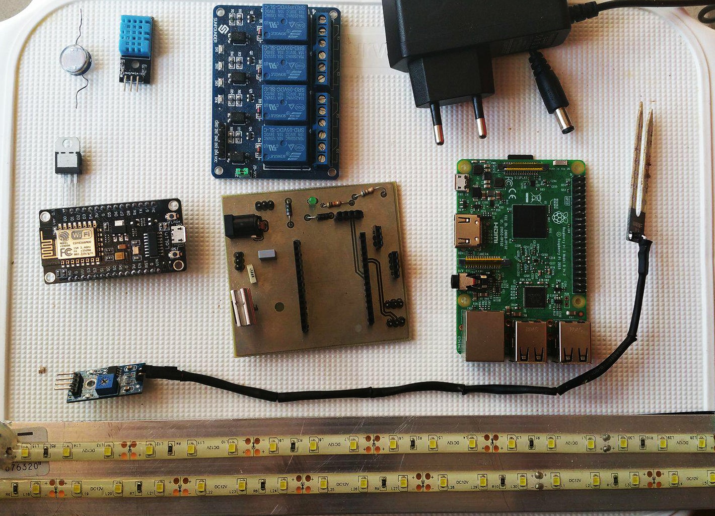

Electronics:
- 1 x NodeMCUv3 µc - 4.29€ - Amazon
- 1 x DHT-11 humidity& temperature sensor -1.18€ - Amazon
- 1 x LDR - 0.93€ / 5pcs - Amazon
- 1 x YL-38 & YL-69 soil moisture sensor -3.27€- Amazon
- 1 x blue led - 3.77€/300pcs- Bangood
- 1 x 680 ohms resistor -0.62€/100 pcs - Aliexpress
- 1 x 10 kohms resistor -0.63€/100pcs - Aliexpress
- 2 x 1N4007 diode -0.19/pcs - Farnell
- 1 x 30 cm white LED strip -9.99€/5m - Amazon
- 2 x 1 solid state relay modules or 1x 2 solid state relays module - 7.59€- Amazon
- 1 x DC 12 V water pump - 11.99€ - Amazon
- 1 x LM7805C -0,29€ - Reichelt
- 1 x 0,1 µF capacitor - 0,03 € - Reichelt
- 1 x 0,33 µF capacitor - 0,03€ - Reichelt
Total price of : 43.71 € in my country, that could change a bit in yours but it gives you an idea.
Power equipments :
- 1 x DC 12 V 2A power supply is enough for powering the whole system - 3.71€- DealExtreme
- Jack connector in my case : -1€- Reichelt
- 1 x 5 V power supply for the NodeMCU, if you're willing to print my Eagle PCB you can avoid this as the 12V will also power the nodeMCU. (See Step 9)
Other components required:
- 1 x Android phone
- 1 x 300mm x 5 mm aluminium plate (This is used to hold and cooldown the LED strip, you can use ANY configuration you want as long as you're able to light your space properly) I found mine in the local workshop store.
- Tubing adaptable to your water pump, in my case: Amazon
Software required:
- Arduino IDE on the computer
- Blynk app on your smartphone (either Android or IOS)
Step 2: The Sensors


To enhance the life of our plants the main goal will be to monitore the following parameters :
- Temperature of the air, using the DHT-11.
the air temperature is an important factor acting on plant growth. Each variety have their own perfect temperature so the choice of plants will be directly linked to it.
The DHT-11 will also be used to analyse the humidity of the air, moisture in the air is affecting growth depending on the variety of plants, some evolved with low moisture in the air meanwhile some others need a wet environment to grow. - Along with the temperature, the moisture of the soil is widely acting on the development process, we will analyse this parameter using a YL-69 & YL-38 soil moisture sensor.
- Last but not least, the light intensity will be checked using a Light Dependent Resistor (LDR). Without entering too much in details, the working principle is the following: it is a device whose resistivity is directly linked to the amount of light absorbed by the photo-conductive material. If you are interrested, Here are more informations and the maths about it.
Analysing those parameters is incredibly powerful to help our plants growing and take care of them.
Step 3: The Actuators


The automatisation part of the project is done by simply using the data collected by our sensors and to activate some actuators in order to have an impact on the growing environment of our plants:
- A water pump will be triggered during a settable duration whenever the soil moisture detected is too low. This will be done by the microcontroller with some solid states relays. With this system, our greenhouse will be watering when our plants need it and we'll be able to leave the system running as long as there is enough water inside it.
- A light system composed of low consumption, high intensity LED strip, will be turned ON, during a previously established duration, whenever the light intensity drops under a certain limit. This done, we will be able to give the plants their perfect duration of light/day, this will signatifically increase the growth rate, while consuming the less power possible.
Note : Why do we use white LEDs instead of the common blue/red combination?
According to Nasa and early researchsconcerning the effects of different light spectra on plants, we found that red and blue lights offer the best support for photosynthesis, which is the process used by plants to transform light into the energy needed for growth and flowering. Further investigation pinpointed more specific effects of different light wavelengths on plants grown indoors.
For example Green Lights penetrates through thick top canopies to support the leaves in the lower canopy.
For our project we will be using full spectrum white LEDs that are providing the full range of visible wavelengths, however you could chose to build a red/blue LEDs light system by combining 2/3 of red LEDs with 1/3 of blue ones. Here is a pretty interesting article from Nasa about how they're developing gardening in the harsh conditions of space : link
I am aware that this project is not perfect in many ways, we're not adjusting the overall air temperature or humidity for example, we are using rather cheap sensors etc... and I will dedicate a whole step for evolution perspectives at the end of this instructables. This said, following the steps will give a working system that you will be able to custom in your way.
Step 4: Why Are We Using the NodeMCU Microcontroller?


- Cheap
The NodeMCU as well as any arduino board are inexpensive and cost from 3€ to 25€ for the most of them. This is completely affordable compared to industrial microcontroller, Field Programmable Gate Arrays (FPGAs) or Application Specific Iintegrated Circuits (ASICs). - Already connected
The NodeMCU is based on the esp8266 module, which is a wifi module. One of the main points of using this microcontroller instead of a more common arduino board is that the esp8266 is already connected and ready to use. Moreover the nodeMCU was made as a nodejs style network API that speeds up the IoT projects developments. - Language support / Cross-platform
NodeMCU is an open-source firmware and development kit that helps you to prototype your IOT product within a few Lua script lines. NodeMCU is compatible with the Arduino IDE that is working on Windows, MAC-OS and (many) linux distributions. With this your code is easily exportable to another system. - Free, simple programming environment
The Arduino IDE is a free open source IDE that is often updated by the arduino dev team and widely supported accross the internet with one of the most active community online. The software is open source, many people started to write libraries, to publish online projects and a wide range of tutorials.
Some useful links:
Step 5: Installing the Arduino IDE


You will need the Arduino Integrated Development Environment (IDE) software, here is a quick link for downloading the latest version.
Let's process as follows (if you already have the arduino IDE installed and fully working you can skip the following list and go to either the librairies or the Blynk installation) :
- Select your Operating System.
- Download and install the Arduino IDE as shown in the pictures.
Step 6: Install NodeMCU Requirements


As we are using the NodeMCU microcontroller, we need to add this board to the arduino IDE:
- Open the Arduino IDE Go to "files" and click on preference(Picture 1)
- Copy the following link in the "Additional boards Manager" :
http://arduino.esp8266.com/stable/package_esp8266com_index.json (Picture 2) - Click OK to close the preference tab.
- Go to Tools, put the cursor on Boards: " ..."
- Click on the Boards Manager Type esp8266 on the search bar and install it.(Pictures 3 & 4)
Step 7: Installing the Librairies


We will need some libraries for the communication with the sensors.
- For the DHT11 we're using the DHT.h library from Adafruit.
- We will also need the Adafruit_Sensor-master library in order to use the DHT one.
- For timers we'll be using the SimpleTimer.h library.
- For the wifi module, esp8266 we're using the ESP8266WIFI.h. (This should be already installed after the previous step)
- For the Blynk app, we're using the BlynkSimpleEsp8266.h
In order to install the previously mentionned libraries you have to manually download each library. Note that this technique will provide you the latest librairies in date:
- Go to "Sketch" -> "include library" -> "Manage Libraries" (Picture 1)
In the search bar type Blynk, select the first one and install it. (Picture 2)
In the search bar type :DHT.h, select the one from Adafruit and click on install.
For the SimpleTimer library, download the document : I also included the DHT and Blynk libraries, but if you've done the two first steps we're sure that you've got the latest versions of these libraries and that you're installation is up to date.
- Copy the SimpleTimer folder and paste it into your Arduino/libraries folder. (You should see the previously downloaded libraries as shown picture 3.)
- Repeat this action for the Adafruit_Sensor-master library.
- Restart your Arduino IDE.
Attachments

Step 8: Installing and Setting Up Blynk


- Pick up your phone and connect to your smartphone store.
- Type "Blynk" in the search bar and download it(Picture 1)
- Once you've downloaded the app, you need to create a new account by registering your e-mail and a password
- Click on the "+"
- Chose a name for your project, mine is "Test"
- Select the "NodeMCU" device by scrolling the list down (Picture 2)
- Keep "WIFI" for the connection type then hit "create".
Note that your auth token should've been sent to your e-mail address(Picture 3)
Once you've done that, you're ready to wire up everything and start coding !
Step 9: I Made It Easier for You


I've created a fully working PCB using Autodesk Eagle software.
You can easily print it using some famous websites or the nearest FabLab. I tested three versions of the PCB and just linked the best one in my opinion. This will ensure you an industrial grade PCB and will make things easier.
Note : If you want to solder the LM7805C properly I ask you to read the datasheet linked here.
- Go to application informations
- And Create the same wiring as the Figure 1 shows.
This will ensure having a fixed output voltage.
Attachments
Step 10: Wiring Up the Sensors


You've got two views for the wiring the second picture is the schematic.
To be as clear as possible connexions are the following:
NodeMCU :
- D1 ----- NodeMCU GND (*)
- D2 ----- dht-11 VCC
- D5 ----- ldr VCC
- D6 ----- soil moisture VCC
- D8 ----- dht-11 DATA
- A0 ----- soil moisture DATA_Diode AND LDR_Diode (**)
Note :
The (*) are explained in the next step.
DHT-11 :
- VCC ----- NodeMCU D2
- DATA ----- NodeMCU
- GND ----- NodeMCU GND
Soil moisture :
- VCC ---- NodeMCU D6
- GND ---- NodeMCU GND
- D0
- A0 ---- NodeMCU A0 through 1N4004 Diode (***)
LDR( The sense of wiring doesn't matter for the LDR, just take it in front of you and decide which leg is "Right" and which is "left") :
- Right ---- NodeMCU A0 through 1N4004 diode (****)AND GND through 10 K Resistor (*****)
- Left ---- NodeMCU D5 (******)
Step 11: More Information About the Previous Step
(*) We need to wire up the D1 port of the NodeMCU to GND to make the NodeMCU being able to load and start the code again after power cycle. Without wiring D1 to GND when you will upload your code on the NodeMCU it will work fine, but if you unplug the power cable, then plug it again, the code will be forgotten.
(**) As we have only one Analog port ( A0 ) and two sensors outputing an Analog value ( the LDR and the soil moisture sensor) we will need to do something called multiplexing in electronics.
The term itself sounds harsh, but the principle is rather simple :
- we will start with both sensors OFF (by OFF i mean without current flowing through them)
- then we will send current through one of the sensor with a digital Port, listen to what is coming on the A0 port: here we've got the value outputed by the first sensor.
- We will then turn OFF the first sensor, and turn ON the second sensor, listen again on A0: we've got the value sent by the 2nd sensor.
- Repeat this process.
(***) & (****) As shown on the schematic of sensors and the main eagle schematic, we're using 1N4004 diodes with the sensors that are communicating with the Analog port A0. This is necessary to avoid any troubles between the sensors, let me explain. Without the diodes, when you turn ON one of the sensors the data will flow from the sensor to the A0 port, but also to the 2nd sensor, because this one is also wired up to A0. The diodes are allowing the current to flow only from the sensor to the Analog port, with that there is no pollution between both sensors anymore.
(*****) The LDR is connected to a pull down resistor, this is mandatory when you're reading through a microcontroller. This is fully explained in that link
(******) On the schematic you can see that I wired up a blue led with her resistor, this is totally optional and is meant to show when the LDR is alimented and that our microcontroller is analysing the light intensity.
Step 12: Wiring Up of the Relays.


Now we will wire up our relays as follows :
Note :
If you have a 2 channels relay module, the VCC/ GND connection should be done only once (as you've got only one VCC pin, one GND pin one IN1 -> D4 and one IN2 -> D7.)
NodeMCU
- D4 ---- Relay 1 IN
- D7 ---- Relay 2 IN
- 3V ---- Relay 1 VCC AND Relay 2 VCC (*)
(*) I added 5V pins on my eagle board to directly wire up the Relays with 5V instead of 3V, so if you've made your own board you can either wire the relays with 3V on the VCC or with a 5V output pin.
Relay 1
- GND ---- GND
- VCC ---- Either 3V output of NodeMCU OR 5V output if you've printed the board from my eagle file
- IN ---- NodeMCU D4
Relay 2
- GND ---- GND
- VCC ---- Either 3V output of NodeMCU OR 5V output if you've printed the board from my eagle file
- IN ---- NodeMCU D7
Once this is done, we're ready to test it out. Time for Coding !
Step 13: Setting Up the Pump and the LEDs


Note :
For the LED lighting system I just took the LED strip, cut it where it is showed with the dots, removed the rubberband behind it and stick it onto the aluminium bar.
I put a On/Off switch but this is totally optional and not really needed for the project.
Connecting the LED strip system:
- Wire up the GND wire of the LED strip to the common GND of the system.
- The "+" wire of the strip to the Common terminal of the solid state relay ( Middle one)
- Connect the NO (Normally Open) terminal of the solid state relay to the +12V.
Repeat the process for the water pump :
- Red wire to Common terminal of the solid state relay.
- Black Wire (GND) to the common GND.
- NO terminal of the 2nd Relay to the +12V.
Step 14: The Full Code.
Here we are, finally against the final boss of the first round... the coding.
You have to connect your NodeMCU to the computer using a conventional usb cable and download the file linked to this step, which is the arduino code for the project. The code:
The first thing you need to do is to edit the code with the ssid and password from your wifi in the Garden code as well as the auth token sent to your newly registered e-mail address as shown below:
We will go though the code in the next step, but first i'll show you how to install and setup the "Blynk" app, so we'll be able to understand every lines of the code.
Step 15: Setup of the Blynk App.


In the blynk app you must add :
- 4 x"Value Display" widgets, one for each parameters monitored.
- 1 x "SuperChart".
- 2 x "LEDs" .
Note :
Blynk has a free 2000 energy counter, this is perfect for our project, however if you want to add more features you can buy some energy and add some pretty useful widgets.
We then have to setup the previously downloaded widgets:
- Click on the first "Value Display" call it temperature and select the V0 input (In the Virtual menu on the left) (Picture 1)
- Set up the reading rate to push mode. (*)
- The second "Value Display" is called light and has V1 as input, push mode of reading rate.
- The third is called "Humidity" and linked to the V2 input pin I set up the reading rate to push mode.
- The last one is called "Soil Moisture" and linked to the V3 input pin I set up the reading rate to push mode.
- The first LED is called "pump" and is linked to the V4 input pin, this LED will show us if the pump in ON or not.
- The second LED is called "lights" and is linked to the V5 input pin, this LED will show us if the artificial lights are ON or OFF.
- For the SuperChart add the name of the 4 variables, Temperature, Humidity, Soil moisture and Lights and set up the corresponding PINs by clicking on the setup button on the right of each name.(Picture 2)
- You can order everything as you wish the Picture 3 is showing you what is my actual configuration
(*) Push mode will make Blynk refresh his value whenever the Microcontroller is sending it with the Blynk.VirtualWrite() function explained in the "Sensoring functions" part below.
After that is done, we can start to go through the code and to explain every parts of it.
Note:
On the SuperChart I advise you to Show the legend, and to change the color of each chart in order to see things as clearly as possible.
Step 16: Review of the Code.

Note:
If you want to debug your code, don't forget to go to "tools" and to set the proper parameters as shown in the Picture 1:
- Board : "NodeMCU 1.0 (ESP-12E Module)
- Flash Size : "4M(1M SPIFFS)"
- Debug Port : "Serial"
- Debug Level : "None"
- IwIP Variant : "v2 Prebuild (MSS = 536)
- CPU Frequency = "80Mhz"
- Upload Speed: "115200" (**)
- Port : You port COM
(**) When you've got the Serial window open don't forget to put the same value on the bottom right corner, without that you will have random characters on the screen.
The code structure is rather simple :
- Librairies declaration
- Pin defintion
- Variables definition
- Thresholds definition
- declaration of the timer
- Blynk widgets declaration
- We then got the setup function :
- Then we've got two functions that are activating, reading the sensors values then publishing the value on Blynk
- And finally two functions that are processing the data coming from the previous functions, are triggering the actuators if needed, and lighting the LEDs if so
Once you've understood this, you normally have a fully functionnal system, autonomous and connected to your smartphone everywhere you go via Blynk.
Note:
One important thing to be aware of is that if your app or phone is not connected, it's not a problem the data sent by your NodeMCU is buffered and stocked on the Blynk server, then sent to your app whenever you're connecting.
Attachments
Step 17: Second Part of the Project


If you're reading this part it is because you've got a fully working project communicating with the blynk app but now you want to have the control on every part of the project, or just learn more about it.
For the second part we will use the same sensors/actuators/nodeMCU to gather data and transmit it. But instead of sending it to the Blynk servers where who knows what's happening with our datas, we will create our own server saving the datas and being accessible over the web.
We will make our nodeMCU communicate with the RPI server using the MQTT protocol, the next step will be dedicated to the understanding of this protocol and why it is currently widely used in IoT.
The Raspberry PI will be hosting the MQTT server (Broker) using the Mosquitto packages as well as the node-red script for communicating with the nodeMCU and the dashboard interface.
From the nodeMCU we will emit/receive MQTTs messages using the PubSubClient.h library to connect our MQTT server.
Requirements:
- 1 x Raspberry pi ( I have a Raspberry pi 3 model B which is the latest version available, but any raspberry pi 2 would work as well) -32.19€ - Reichelt
- 1 x 8 Go OR higher micro SDHC card ( Way better if you can find a class 10 micro sd card )-9.99€- Amazon
- 1 x Usb cable for powering the RPI
With those new parts, the total price of the project is now up to :85,90€
Note : I will explain how to setup EVERYTHING on the next steps, but before starting be sure that you've gathered the few components listed.
Step 18: Installing Rapsbian on the Micro SD Card


Note for beginners with RPI:
The Raspberry pi has no hard drive included because of that you need to mount the OS on the micro SDHC card. The following steps might seems really overwhelming if you're not experienced, I felt the same thing on my beginning, just take a deep breathe and follow the steps, everything should work without any doubt.
Here is a direct link to the latest version of NOOBS that you have to download. NOOBS stands for New Out Of the BOX Software. Select the full version of NOOBS and download the .zip version (Picture 1 & 2)
While it is downloading you need to format the micro SD card :
- Visit the SD Association website and download the latest version of SD Formatter software for Windows or Mac OS. ( The RPI can only read both FAT16 and FAT32formats)
- Follow the instructions to install the software.
- Insert the SD card into the computer (you should have a micro SD - SD adaptater in the package when you buy the micro sd card)
- In the SD Formatter select the right drive letter for the SD card and format it.
Be really careful when you select the letter, check twice if it is the right drive for the SD card and not something else
You then need to extract the .zip archive select all the files from the NOOBS folder and copy them onto the SD card.
You can then eject the SD card.
Step 19: First Boot on NOOBS

Note :
You can now put your micro SD card in the RPI, then plug the power cable.
You will be offered a wide choice of OS on the first boot, you need to install the Raspbian OS :
- Tick the box near Raspbian and click on install (Picture 1)
- Raspbian will then run though its installation, this can take several minutes.
- The installation is finished when the Raspbian desktop is appearing with the raspi-config tab open where you can select your time/location and several other parameters.
- Open a terminal : and type the following lines:
- First update your raspbian package list with the following command :
sudo apt-get update - Then upgrade your packages to their latest versions with the following command :
sudo apt-get dist-upgrade
Note :
You should do this regularly to get your installation up to date. - First update your raspbian package list with the following command :
Step 20: The MQTT Protocol

The Message Queueing Telemetry Transport Protocol (MQTT), is widely used in IoT applications nowadays.
In this step i'll try to explain how this is working and why it is expected to become the main protocol in IoT applications in the near future.
MQTT is a publish/suscribe based lightweight messaging protocol for Machine to Machine (M2M) communication, on top of the famous TCP/IP protocol. For a known example, MQTT has been used by Facebook messenger application, which needed a connection to Facebook's servers without killing the battery life.
Some key points of MQTT :
- It requires low bandwidth and a small code footprint.
- Open source & royalty free.
- Easy to implement.
- Multiple quality of service levels.
- Simple command messages.
- Durable connections.
- Last will and testament services.
- Small messages header.
- Distribution type : One-to-many
Some Vocabulary and basic concepts:
- Broker :
The broker is primarily responsible for receiving all messages, filtering them and decide who's interested in this type of message and then publish the message to all suscribed clients. - Messages :
Messages are the information that you want to exchange between your devices, it might be a command, data coming from sensors or a notification for example. - Topics
One of the most important concept of MQQT is the Topics, these are the way of registering interest for incoming messages as well as "where" you want to publish your message. Topics are represented with strings separated with slashes. - Publish / Suscribe :
This means that a device can publish a message with a defined topic on the MQTT broker and only devices that are suscribers to this topic will receive this message.
You should check the picture to get an overall understanding of how the vocabulary explained before is working in reality.
One example for understanding:
In our case the MQQT BROKER will be held on the raspberry pi as we will use Mosquitto. Our way of communicating will be to send data coming from our sensors to the broker. The nodeMCU will PUBLISH the data coming from the sensors on the Mosquitto BROKER on the TOPIC : /Garden/SensorX.
For example publish the temperature coming from the DHT-11 sensor, on the topic /Garden/Temperature on the Mosquitto MQTT Broker.
At the same time the Raspberry pi will be running our Node-red script, this node-red script will allow us to communicate with the nodeMCU and to see the data coming from it on the dashboard.
What is important about this, is that in dashboard, the gauge and the chart dedicated to the temperature of the air, will be suscribers to the /Garden/Temperature topic. So whenever the nodeMCU sends data on this particular topic, the dedicated gauge and the chart will be updated.
In the same idea, the gauge showing the soilMoisture sensordata will only be updated when the topic /Garden/SoilMoisture will be published by the SoilMoisture sensor publishing the data in this topic.
When we want to send a command from the node-red script to the nodeMCU the opposite need to be done. We will Publish the command on a topic /Garden/Command and the nodeMCU will get the message because we wrote in the arduino code that the nodeMCU is a suscriber of the topic /Garden/Command.
If we want to switch ON the lights, we will make the nodeMCU suscriber of the topic /Garden/Command/Lights, from the node-red script we will publish the message "ON" on the topic /Garden/Command/Lights and the nodeMCU will get it as it is a suscriber of the message.
A useful link to get more informations about the subject.
Step 21: Installing the Broker : Mosquitto

In this step we will install the Mosquitto broker. For additional informations you can follow this link
Note :
For beginnerr on linux, the command that you're typing in the terminal the commands that you are typing are AFTER the $ sign in the command line.
First we need to update the repository :
- Open a terminal
- Type the following command :
- pi@raspberry:~ $ wget http://repo.mosquitto.org/debian/mosquitto-repo.gpg.key
- Type the following command :
pi@raspberry:~ $ sudo apt-key add mosquitto-repo.gpg.key
- Then make the repository available to be installed with apt with the command:
pi@raspberry:~ $ cd /etc/apt/sources.list.d/ It should print this location :
pi@raspberrypi:/etc/apt/sources.list.d $- Then Run the following command :
pi@raspberrypi:/etc/apt/sources.list.d $ sudo wget http://repo.mosquitto.org/debian/mosquitto-jessie.list
- We then go back to the root directory :
pi@raspberrypi:/etc/apt/sources.list.d $ cd
- And we update the packages again :
pi@raspberry:~ $ sudo apt update
- We then need to install it properly :
pi@raspberry:~ $ sudo aptitude install mosquitto
- You need to type Y then enter to process at the installation.
To TEST our installation just run :
pi@raspberry:~ $ mosquitto -v
It should print you :
Note:
This command returns the Mosquitto version that is currently installed and also tries to initialize Mosquitto again. Since Mosquitto is already running it prompts an error message. Don’t worry Mosquitto is properly installed and running if you see a similar message.
Step 22: Node-red and the Dashboard Node


Node-red is already installed with the NOOBS package and the raspbian Jessie OS.
We first we have to do an update /upgrade of the system to be sure everything is clean:
- pi@raspberry:~ $ apt-get update
- pi@raspberry:~ $ apt-get upgrade
Then we want to add the "dashboard" node to our system, in order to make the UI. I'll provide you two ways to do it, keep in mind that the first is way easier but sometimes provides an error.
First method :
- type :
pi@raspberry:~ $ node-red start
- Once the system is initialised, open a web browser and go to the specified IP address. (See Picture 1) with the port : 1880
- You should have the (Picture 2) interface.
- Go to the menu on the right and find "Manage palette"
- on the new window click on install, go to the search bar and look for Dashboard, click on install as shown in (Picture 3)
- Run through the installation, when it's ended you must refresh the node-red page you must have now a new box on the right saying Dashboard (Picture 4) as well as a "dashboard" section with the nodes presented on (Picture 5).
Step 23: NodeMCU and MQTT
We will now analyse the code running on the NodeMCU and how to suscribe to a topic or publish on the MQTTBroker.
First we need to install as we did in the step 7 "the PubSubClient.h"Library, so we can make our NodeMCUcommunicate with our Mosquitto MQTT Broker running on the RPI.
- Add the PubSubClient.h library to your Arduino IDE and install the library as shown previously
You can download the full code linked in this step too.
Here's a preview of the full code :
Step 24: The Dashboard


Note :
If you want to access Node-red from another computer on the same local network you can go to your browser and put the "IP adress: Port" on the searching field and hit Enter.
For example if the node-red service is running, I can connect to the RPI node-red service from my windows computer by putting : http://192.168.1.16:1880in the searching field.
Then i'm able to create node-red scripts directly from my windows computer.
Second Note :
In Node-red you can directly copy past a script done on another computer. You can find this code on the bottom part of this step, instead of creating it you can simply take the code copy it go to node-red, click on the menu on the right -> import -> clipboard and paste the code here, it will automatically create the same dashboard as I did.
If you want to create everything to understand how it is done, it is time to create the dashboard and the flow :
- First Gauge:
- We will create first gauge of the dashboard : showing the light intensity measured:
You first need to take a MQTT input node as shown in Picture 1
Double click on the node to open the menu of Picture 2
In the "server" field put "localhost:1883" as shown in Picture 2
- In the "Topic" put Garden/Light
- On the left menu scroll down to find the Gauge node in the Dashboard collection
- Drag and drop it on the working field
- Double click on the node to open the menu
- On the "Group" click on the little pencil on the right of the case to create a new group (Picture 3)
- I called it Sensors as shown in Picture 4
- Link the MQTT input node with the Gauge node by clicking on the grey box on the right of the MQTT node and reaching the grey box on the left of the gauge node.
- Drag and drop it on the working field
- We will create first gauge of the dashboard : showing the light intensity measured:
- You then need to repeat this process to create 3 other gauges respectively for the Soil Moisture, the temperature and humidity of the air.
- The Next step is to link ONE chart to every MQTT nodes, so you need to drag the chart node on the left menu and drop it on the working field.
- As long as you're linking the chart it should work.
- You should still double click on the node to verify that it is part of the Garden group
- Then link every MQTT outputs to this chart.
- I Then created another tab on the Dashboard and two more groups in this tab, to link ONE chart to ONE MQTT node, in order to display on another tab of the dashboard the evolution of each values.
- Click on the Dashboard -> "+ tab" (Picture 4)
- Edit the name of this new tab if you wish
- Click on "+ group" on your new tab and rename it
- I chose to do 2 groups, one for digital sensors and one for analog sensors.
- Click on the Dashboard -> "+ tab" (Picture 4)
- The Final montage looks like the (Picture 5)
- The first tab of the dashboard is as shown in picture 6.
- While the second tab looks like the picture 7.
- To visualise the dashboard just go in your borwser and type " http://IP_address:Port/ui/" for me it is :
http://192.168.1.16:1880/ui/
Attachments
Step 25: Command the Actuators


We will add some buttonscontrolling the relays on the dashboard.
Note:
I'll again provide you the code of the node-red script in a .txt file so you can easily import it.
The thing to understand in this step is that the commands sent from the node-red script are read and processed in the callback function on the NodeMCU. We will either publish ON or OFF on the desired topic that will be understood by the nodeMCU and turn ON or OFF its actuators.
- You need to add two nodes of MQTT Output and configure them as we did in the step before.
- Drag and drop two nodes "Button" from the Dashboard library and configure them as shown in Pictures
- I put these new buttons on the first Tab we created.
In the NodeMCU we need to configure the callback function to react on the trigger events as shown below :
Step 26: Connecting to the Internet : Port Forwarding
For now you can acces our dashboard from the local network but not yet from the internet and hHere is the only step I cannot really help you because it depends on your internet provider.
You will need to do something called port forwarding between your internet router and the RPI.
As explained on the Raspbian website here is a quick explanation of what this concept is :
- Port forwarding
One method is to set up port forwarding on your router.
To do this, you must change the configuration of your router to forward all inbound traffic from the internet on a specific port to the local IP address of your Raspberry Pi. Most routers have this feature available.
However, every router is different so you will need to consult your router's user manual for instructions. The settings can be tricky if your Pi is behind a firewall or if there is more than one router.
One disadvantage of port forwarding is that it exposes a network port on your private LAN to the public internet. This is a known security vulnerability and must be managed carefully.
I am deeply sorry to not make this step as detailled as some of you would need it, but do not hesitate to ask question on the comment section below I will give my best to help you guys.
Step 27: Improvements
- Security
For a project like this we won't be needing a huge security system, but as internet can be highly dangerous we will still create some barriers. I will check this asap, I already have some ideas but if I understood well we will need to change the MQTT library used on the Arduino IDE as PubSubClient.h doesn't support TLS certificats.
On the RPI part we will generate our certificats using open-ssl, this part should not be tricky. I will update the instructables whenever this is ready to use.
Certificats and TLS :
Transport Layer Security is a cryptographic protocol that provide communications security over a computer network. It aimes to provide privacy and data integrity between two communicating entities. The whole protocol is using public-key cryptography/message authentification or/and symmetric cryptography. I highly invite you to follow this link if you want more informations about it.
- Consumption
The next thing that we could optimize would be the power consumption. We could for example put the nodeMCU in sleep mode between the analysis phases, using a built-in timer to wake it up. I'll give it a go after setting up the security system.
- Water level sensor
Something highly useful would be to put a sensor for triggering a buzzer NOR notification NOR email NOR red LED or anything else you can think about whenever the water level is below 30 % of the tank capacity. This would add to the overall automation idea and would in the end be pretty useful. (One of my current idea would be to implement this using a linear hall effect sensor with a magnet fixed at the bottom of our water tank.)
- Improving sensors
To make our system more reliable we could use better sensors, this would obviously add to the overall cost, but for example replacing the DHT-11 by a DHT-22 woud be a first step.. Then If you really want reliability and stability industrials sensors could be purchased.
Step 28: Thank You

I am currently creating a 3D model using Autodesk Inventor, but that's new for me, I expected to give you guys a perfect 3D model but it seems easier than it really is. I'll upload it asap.
Anyways that was a super experience to write this first instructables, I hope you guys enjoyed it as much as I did.
Please consider voting for this project in the actual contests if you liked it.
Thank you for reading it and see you later, cheers!

Participated in the
First Time Author Contest 2018

Participated in the
Epilog Challenge 9

Participated in the
Arduino Contest 2017

Participated in the
Remote Control Contest 2017


