

Introduction: Upgrading From ANET3D V1.5 to MKS Gen 1.4


![How to Load New Firmware on [BTT] Bigtreetech TFT Displays](https://content.instructables.com/FCM/ENW4/K8LRQ8UD/FCMENW4K8LRQ8UD.png?auto=webp&crop=1%3A1&frame=1&width=130)
This instructable is for upgrading from an Anet 3D Ver 1.5 to an MKS Gen 1.4.
This instructable assumes that your Anet board was working or currently is working and running Marlain 1.1.9.
The items I will be covering are as follows:
1. Wiring and plug changes.
2. Marlain software changes.
3. Quickly calibrating steps/mm for X-axis, Y-axis, Z-axis, and the extruder.
Step 1: Tools and Supplies Needed
Tools:
- Wire cutters
- Wire strippers
- Small and large screwdrivers
Exacto knife or very small flat head screwdriver.
Supplies/items:
- Stepper motor drivers for the MKS board. (I am using LV8729's)
Step 2: Label All Wires Unknown to You.

Make sure you label any and all wires unless you are sure where they go.
Note: on older versions of the Anet boards the power supply wires are swapped, so check before removing them.
Step 3: Where to Plug in All of This?

Click on the above image to see all of the labels.
- Stepper motors; plugin as shown in the diagram for the MKS board.
Connectors needing one wire changed:
- Each of the end-stop connectors
- What we will do is move a pin in the three connectors.
Different pin count for the thermistors; Anet 3-pin, MKS 2-pin:
- The thermistor connectors are not the same.
- The two fan connectors have the 2-pin connectors we need and on the MKS board, we don't need these connectors for the fans.
All of the other wires have screw terminals to connect them.
Next step will show the plugs and wire changes.
Step 4: Changing the End-stop and Thermistor Connectors.


If you are unsure about how to make these changes to the connectors, please watch the video. (not my video)
- The end-stop connectors.
- We need to move the black striped wire to the middle (see photo), we do this by using the Xacto blade to depress the connector latch down to release the wire then slip that wire into the middle spot. PLEASE make sure you move the right pin or you could end up shorting out (KILLING) your new MKS board when the end stop switch is activated.
- Do this for each end-stop connectors.
- Next; we need to remove the connectors from the plugs for the thermistors.
- Remove the connectors from the plugs for the two fans, then cut off the connectors. The fans will be connected to screw terminals and the connectors we need for the thermistors.
- Using the two 2-pin connectors; insert the connectors for one of the thermistors, repeat for the other connector.
- Plug in the connectors as shown in the diagram for the MKS board.
You will need to connect the hot-end cooling fan to the power supply and the parts cooling fan to the location shown on the diagram.
Next step is making the changes to Marlain.
Step 5: Making the Needed Changes to Marlain 1.1.9
The following assumes that you have been running Marlain 1.1.x and if you are not running version 1.1.9 then also how to carry your current settings for the Anet setup into this new version.
Start Arduino IDE and load the Marlain 1.1.9.
- Open the Configuration.h tab
- Find #define MOTHERBOARD
- Change to #define MOTHERBOARD BOARD_MKS_GEN_13
- Find #define X_MIN_ENDSTOP_INVERTING
- Change X_MIN, Y_MIN, and Z_MIN to true
- Find #define X_DRIVER_TYPE
- Change X, Y, Z, E0, E1 to the drivers you have installed on the MKS board.
- Find #define INVERT_X_DIR
- For my E12 using the LV8729s; I had to make these changes:
#define INVERT_X_DIR true
#define INVERT_Y_DIR false
#define INVERT_Z_DIR false
#define INVERT_E0_DIR true
#define INVERT_E1_DIR false
- For my E12 using the LV8729s; I had to make these changes:
- Find Default Axis Steps Per Unit (steps/mm)
- The steps per mm will have to be updated but measurements and jogging the stepper motors will be required, that will be covered in the next step. Remember this location.
- Find #define MOTHERBOARD
- Open the Configuration_adv.h
- Find //#define Z_DUAL_STEPPER_DRIVERS
- remove the // only if your printer has two Z-axis stepper motors like E10, E12 etc..Note if you don't then don't plug the z-axis into E1.
- Find //#define Z_DUAL_STEPPER_DRIVERS
Turn on the power supply, connect the USB cable.
Save, change to the board type Mega 2560.
Select the com port for the new board.
Compile and upload.
Step 6: See If Everything Is Working.

If you want to use the Anet LCD display on the MKS board see this instructable .
Connect the MKS board with your slicer, access your jog controls, check to see if X, Y, and Z moves (don't home just yet)
NOTE: this board can get power from the USB connector but only for the logic parts of the board and not the steppers or heaters. Make sure you supply 12 Volts during any and all usage of the printer.
Step 7: Quick Calibration of the Three Axis and the Extruder.


This part assumes that you have access to software that can send jog commands and Gcode commands to the MKS board.
The settings and measurements in the steps below are from my setup of my MKS Gen 1.4 with LV8729 drivers using Marlian 1.1.9. on an E12. Note; your numbers will have to be utilized to obtain your correct settings.
Open your software and connect to the board.
- Send M503 to get your current steps/mm settings.
- Find the M92 line and the format should look like this M92 X80.65 Y80.78 Z392.47 E97.82
Start of the X-axis calibration:
- Home the X-axis.
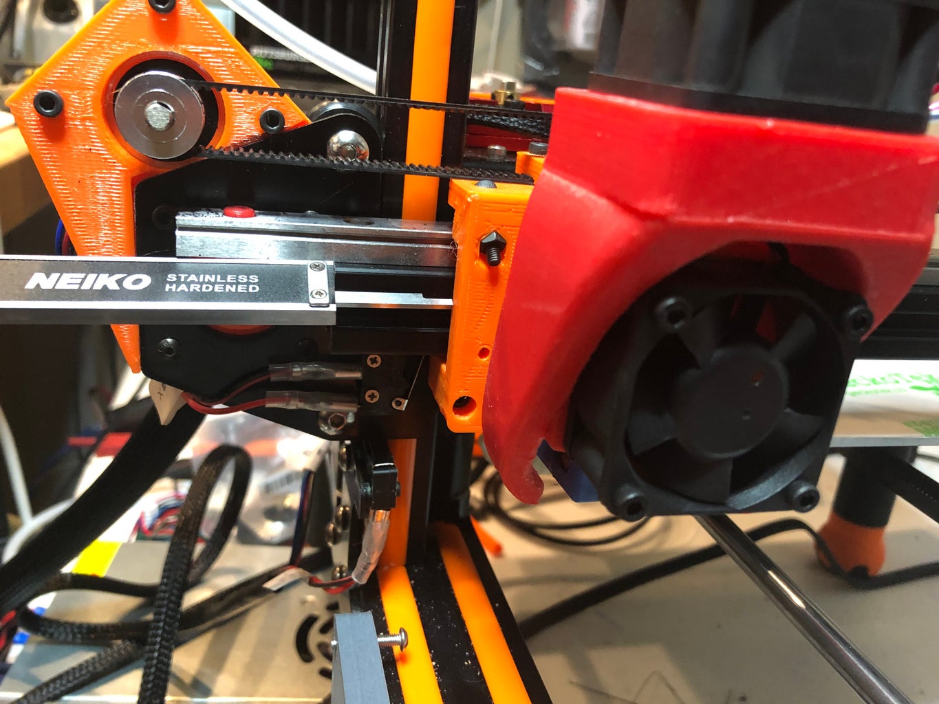
- Move the X carriage out 25mm from the end of the 20x20 rail (see photos) and zero calipers.
- Jog the X-axis +100mm
- Mine moved 24.84 with 80.65/mm
- The formula is the following; 'How far you told it to move' * 'the axis steps/mm' = result / 'what it really moved' = 'new axis steps/mm'
- 100 * 80.65 = 8065
- 8065 / 24.84 = 324.68/mm
- Close but not yet dailed in.
- The next two Gcode commands updates the new X steps/mm.
- I sent M92 X324.68
- I sent M500
- Home the X-axis.
- Move the X carriage out 25mm from the end of the 20x20 rail (see photos) and zero calipers.
- Jog the X-axis +100mm
- Mine moved 101.38
- 100 * 324.68 = 32468
- 32468 / 101.38 = 320.26/mm
- Closer but not yet dialed in.
- I sent M92 X320.26
- I sent M500
- Home the X-axis.
- Move the X carriage out 25mm from the end of the 20x20 rail (see photos) and zero calipers.
- Jog the X-axis +100mm
- Mine moved 99.84
- Now some fun with math, don't ask me to explain how it works, it just works.
- The first set is the last [two sets] lengths of movement and gets the difference.
- 101.38 - 99.84 = 1.54
- The second set is the last [two sets] steps/mm and gets the difference.
- 324.68 - 320.26 = 4.42
- Steps/mm (4.42) / length (1.54) = 2.87
- the needed length (100-99.84) = 0.16
- 2.87 * 0.16 = 0.4592/mm
- Steps/mm for [99.84] 320.26 + [the adjustment number] 0.4592 = 320.72/mm
- I sent M92 X320.72
- I sent M500
Start of the Y-axis calibration:
- Since the Y-axis has a belt system like the X-axis lets set the Y-axis to the same number.
- I sent M92 Y320.72
- I sent M500
- Home the Y-axis.
- Move the Y carriage out 25mm from the end of the 20x20 rail (see photos) and zero calipers.
- Jog the Y-axis 100mm (-100 if starting from the front. +100 if starting from the back)
- Mine moved 100.73 with 320.72/mm
- 100 * 320.72 = 32072
- 32072 / 100.73 = 318.40/mm
- Close but not yet dialed in.
- I sent M92 Y318.40
- I sent M500
- Home the Y-axis.
- Move the Y carriage out 25mm from the end of the 20x20 rail (see photos) and zero calipers.
- Jog the Y-axis 100mm (-100 if starting from the front. +100 if starting from the back)
- Mine moved 99.92
Start of the Z-axis calibration:
- Home all axis.
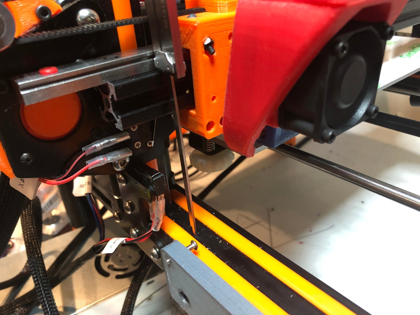
- Jog the X-axis +10mm. This is to move it over so you can measure the top of 20x20 X carriage rail down to the metal part of the 20x40 support below.
- Jog the Z-axis +100mm
- Mine moved 24.55 with 392.47/mm
- 100 * 392.47 = 39247
- 39247 / 24.55 = 1598.66mm
- Close but not yet dialed in.
- I sent M92 Z1598.66
- I sent M500
- Home all axis
- Jog the X-axis +10mm.
- Jog the Z-axis +100mm
- Mine moved 99.92
- [last two sets lengths] 99.92 - 24.55 = 75.37
- [last two sets step values] 1598.66 - 392.47 = 1206.19
- 1206.19 / 75.37 = 16
- 16*.08 = 1.28
- 1598.66 + 1.28 = 1599.94/mm
- I sent M92 Z1599.94
- I sent M500
- Home all axis
- Jog the X-axis +10mm.
- Jog the Z-axis +100mm
- Mine moved 99.96
Start of the extruder calibration:
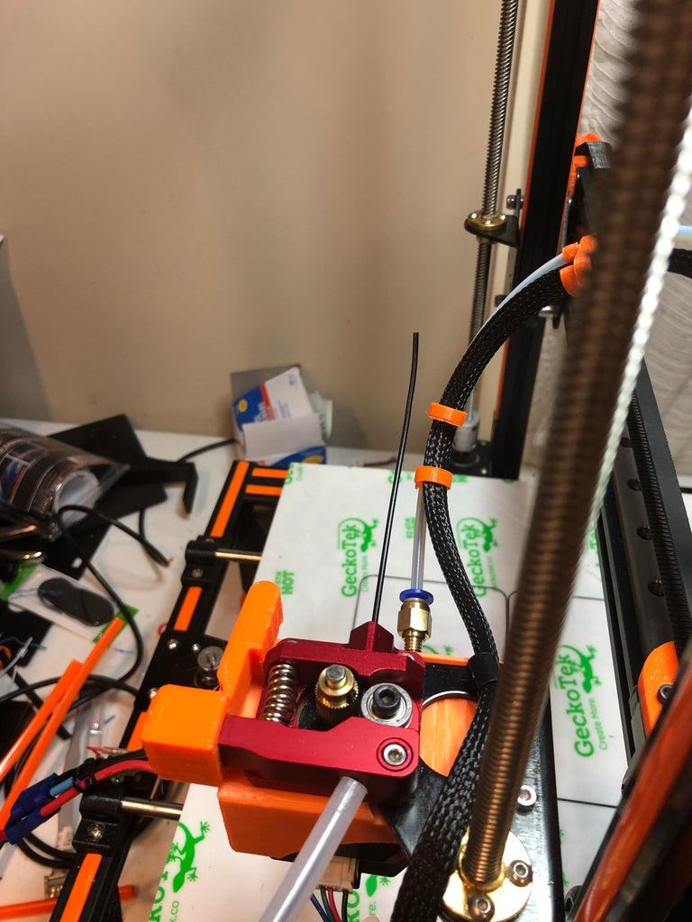
Since you are moving to new drivers I wouldn't recommend calibrating while extruding, if the number isn't right it could try to push too much through the nozzle. I did mine by disconnecting the tube just off the extruder motor then pulling some filament through and cutting it flush at the body (see photo). Next heat up the extruder to 180C, this is in case you have "don't allow cold extrude" enabled. When at temp start the extruder motor calibration.
- Staring with the filament flush at the body of the extruder.
- Extrude 100mm for each run, then measure how much got pushed through.
- Extrude 100mm
- Ended up extruded way more than 100mm, longer than my calipers had to use a tape measure.
- Close to 16 inches = 406.4mm with 97.82/mm
- 100 * 97.82 = 9782
- 9782 / 406.4 = 24.07/mm
- Close but not yet dialed in.
- I sent M92 E24.07
- I sent M500
- Reset the filament to flush with the extruder body.
- Extrude 100mm
- Mine moved 97.26
- 100 * 24.07 = 2407
- 2407 / 97.26 = 24.75/mm
- I sent M92 E24.75
- I sent M500
- Reset the filament to flush with the extruder body.
- Extrude 100mm
- Mine moved 101.28
- [last two sets lengths] 101.28 - 97.26 = 4.02
- [last two sets step values] 24.75 - 24.07 = 0.68
- 4.02/0.68 = 0.169154229
- 0.169154229 * 1.28 = 0.22
- 24.75 - 0.22 = 24.53
- I sent M92 E24.53
- I sent M500
Here is what I changed in the Marlian firmware.
// Xsteps/mm: +80.0, Ysteps/mm: +80.0, Zsteps/mm: +0400.0, eSteps/mm: +0095.0
//#define DEFAULT_AXIS_STEPS_PER_UNIT { 80.65, 80.78, 392.47, 97.82 } Anet3d board #define DEFAULT_AXIS_STEPS_PER_UNIT {320.72, 318.63, 1599.94, 24.53 }
Note: When enabling dual Z motors, Marlian will use the Z-steps/mm for both steppers.


