

Introduction: Upgrading RAMPS 1.4 With TMC2130 Stepper Drivers


Tired of the constant noise your printer is making. Upgrading your RAMPS 1.4 (or most any AT Mega based controllers) with the TMC2130 stepper motors might do the trick.
In this instructable I will not go into the technical babble of PSI, Master/Slave and clock speeds. If you're interested in that I refer you to https://toms3d.org/2017/12/09/tmc2130-guide/ or https://ru-clip.com/video/sPvTB3irCxQ/how-to-make-... or https://hackaday.com/2016/09/30/3d-printering-trin...
Also if anything in this instructable seems unclear, check with those sites.To their credit, I've used them mainly as the source for my upgrade.
Here are some of the advantages I've been reading about:
- Super quiet operation
- Ability to configure via software
- Proper alignment of controller which allows for proper cooling of the driver chips
- Possibility of homing X and Y without End stops (diagnosis allows for the software to recognize the axis bumping into things).
- Potentially with future updates of Marlin the ability to act on missed steps during printing (like Prusa I3 MK3 can do today).
What it boils down to is that these new stepper drivers can be controlled via software and can run in an ultra silents mode (with 256 micro steps). With these new stepper drivers you no longer need to adjust the little pot meters on the driver but instead can tell it via g-codes at how many amps/volts to run.
When buying these steppers online be cautious about how they are delivered. Most of them (on amazon.com) already have all pins soldered to them which is a problem as 4 of the pins are pointing the wrong way.
I've ordered the steppers directly from the US distributor (Filastruder.com) and they come with pins but not soldered on.
In this instructable I will start with the bare stepper driver, solder the pins and create a wiring harness that connects all the right pins on the steppers to the proper pins on the RAMPS 1.4 board.
This instructable will be for the RAMPS 1.4 board but many derivatives use the exact same pin configurations (I will try this out on my KFB 2.0 board).
Step 1: Things Needed


The following items are pre-requisite to this project:
TMC2130 Stepper Driver: $13.99 per stepper from Filastruder (the official US Distributor) https://www.filastruder.com/products/silentstepsti...
In this project I'm replacing all 4 drivers but you could just replace X and Y as they do most of the work
Ramps 1.4 Board (or RAMPS 1.4 Compatible): (if you buy a kit will will get the A4988 drivers that you will be replacing but the price might still be right): $29.99 http://amzn.to/2FqmN51
Soldering Iron/Station: $39.70 http://amzn.to/2FYTgwU
Some fine solder: $9.98 http://amzn.to/2FgkwKe
Marlin Firmware: Free: http://marlinfw.org/ (I'm using version 1.1.8)
wire to connect SPI pins. I'm using old Stepper Wiring as it suits the problem (4 main pins on each driver): $10.59 for 10 http://amzn.to/2G067ii
Dupont wires Female to Female can be used for individual connections. $6.98 http://amzn.to/2FYRVpQ (all the wires you'll ever need)
With all these wires you don't have to do any crimping of your own (just some soldering).
heat shrink tubing for finishing the soldered wires: $7.99 http://amzn.to/2tlT4oN
Step 2: Assembling the Stepper Drivers


The TMC2130 drivers come un-assembled so first we need to prepare each stepper putting the all the pins in the right places.
Very important about steppers. Trinamic seems to be the only company to do it right. Adding the usual heatsinks on top of a chip is a bit of joke as heat travels below the chip through the board. These little boards are build such that the chip will be underneath the board when assembled and the heat sink can be applied on top of the board.
For this project I added the 4 PSI pins as well as the end stop pin (for end-stop-less homing).
I cut the strips of pins in the right size for assebly (row of 8 pointing down), 4 PSI up, 1 Diagnostic up, one down (En) and 2 down (Dir, Step)
First I will solder the top pins to the driver (I'm using a piece of double sided PCB board to place and rest the pins).
Next I place the bottom pins in place on the PCB board and lay the driver on top and solder the downward facing pins.
Once all pins are soldered simply rinse and repeat for the remaining chips.
Before putting the drivers in your RAMPS 1.4 please note that you can remove the three jumpers that used to set your stepping to 1/16th. It is now handled by the software. I removed mine but I've read you may leave them as they no longer are connected to anything (probably did something to the pins that are now pointing up).
Step 3: Wiring With AUX 3 Available


The common setup TMC2130 setup for marlin assumes that the both Aux 2 and Aux 3 on the RAMPS board are available (like the first image of this step). If your are using a LCD with SD Card adapter, Aux 3 is not available and wiring for that situation will be discussed in the next Step.
The wiring image shows how all wires go to the 2 Aux clusters. Also note that three of the 4 wires are all combined and end up on 1 pin on Aux 3
SDI for X/YZ/E0 all go to pin D51
SCK for X/YZ/E0 all go to pin D52
SDO for X/YZ/E0 all go to pin D50
CS for X goes to D53
CS for Y goes to D49
CS for Z goes to D40
CS for E0 goes to D42
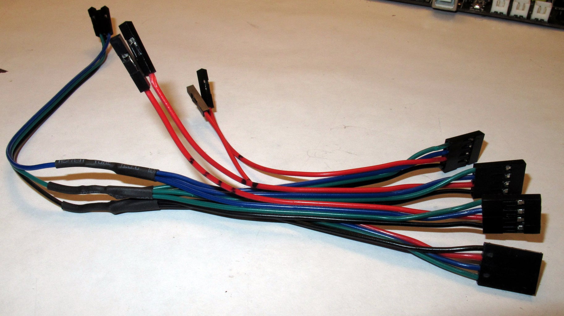
For my project I created a wiring harness that consists of 4 repurposed Stepper wires.
I solder and combined all Black wires into one single black wire ending up with a female connector for a single pin
I solder and combined all Green wires into one single black wire ending up with a female connector for a single pin
I solder and combined all Blue wires into one single black wire ending up with a female connector for a single pin
The Red wires each end up with their own single female pin connector as they each have their own pins assigned on Aux.
Look at the schematic image to see where all wires go
Step 4: Wiring With LCD Installed (Aux 3 Not Available)


Okay, so browsing around the web I can't find a real clean solution to this. It's not that hard to reroute X CS and Y CS to other ports but the RAMPS 1.4 only seems to have one SCK and the two MISO pins which are used by the Card Reader on the LCD Unit.
The solution I've come up with for now is to extend the LCD connector with three pins on top. It's not pretty but it seems pretty sturdy (if soldered well). If you screw it up a new adapter only costs a few dollars on Amazon.com (http://amzn.to/2oNVPdM).
In order to reroute the CS pins, you'll need to update the pin_RAMPS.h file
Change the pins to
DEFINE X_CS_PIN 44
DEFINE Y_CS_PIN 64
//<br>// Steppers
//
#define X_STEP_PIN         54
#define X_DIR_PIN          55
#define X_ENABLE_PIN       38
#define X_CS_PIN           44
#define Y_STEP_PIN         60
#define Y_DIR_PIN          61
#define Y_ENABLE_PIN       56
#define Y_CS_PIN           64
Redirecting these pins works but I'm a bit concerned about some of the threads I'm reading on using the SD card in combination with the TMC2130 (now sharing the same pins as the SD Reader). I will have to runs some more testing once all installed.
The new schematic images will show the new wiring configurations. Just follow the lines.
Step 5: Setting Up the Software
IMPORTANT: YOU NEED Marlin bugfix-1.1.x.zip for this to work. If you find that your distance traveled has changes on any of the axis you have the wrong version.
Once all the hardware is connected (in fairness, I did one Stepper at a time) you will need to make the software aware of the new Drivers. If you are rerouting some of the CS pins because you're using an LCD (adapter) you've already made some changes to the pins_RAMPS.h file but for normal operation most changes occur in the Configuration_adv.h
If you have the latest (or a newer version) of Marlin (I'm using 1.1.8 as of this writing) you can open the configuration_adv.h and search for TMC2130. It will take you right to the TMC2130 section.
First thing you do is uncomment (remove // from in front of) #define HAVE_TMC2130
// @section TMC2130, TMC2208/**
 * Enable this for SilentStepStick Trinamic TMC2130 SPI-configurable stepper drivers.
 *
 * You'll also need the TMC2130Stepper Arduino library
 * (https://github.com/teemuatlut/TMC2130Stepper).
 *
 * To use TMC2130 stepper drivers in SPI mode connect your SPI2130 pins to
 * the hardware SPI interface on your board and define the required CS pins
 * in your `pins_MYBOARD.h` file. (e.g., RAMPS 1.4 uses AUX3 pins `X_CS_PIN 53`, `Y_CS_PIN 49`, etc.).
 */
#define HAVE_TMC2130
Next you un-comment those lines that represent the Stepper motors you will be controlling with the new TMC2130 drivers.
In this case I uncomment all three Axis and the Extruder (E0)
#if ENABLED(HAVE_TMC2130) || ENABLED(HAVE_TMC2208)  // CHOOSE YOUR MOTORS HERE, THIS IS MANDATORY
  #define X_IS_TMC2130
  //#define X2_IS_TMC2130
  #define Y_IS_TMC2130
  //#define Y2_IS_TMC2130
  #define Z_IS_TMC2130
  //#define Z2_IS_TMC2130
  #define E0_IS_TMC2130
  //#define E1_IS_TMC2130
  //#define E2_IS_TMC2130
  //#define E3_IS_TMC2130
  //#define E4_IS_TMC2130
The next section when you scroll down is where you define the power setting of all and each of the divers. In may case I'm pretty much leaving these as is. The first setting R_SENSE I believe has to do with any resistance the motor meets and when to do something with it. Some speculation as I haven't found much on it (let me know if you do)
The second setting HOLD_MULTIPLIER will lower the current by half (or what value you set it to) when the motors are idle. It reduces heat but in some cases also handle the high pitched whining of idle motors.
The third setting INTERPOLATE is what gives the magic to these new drivers so leave it set to true. I will take the 16 steps your RAMPS sends the driver and turns it into 256, giving is the silent and smooth motion.
/**<br>   * Stepper driver settings
*/
#define R_SENSE           0.11  // R_sense resistor for SilentStepStick2130
#define HOLD_MULTIPLIER    0.5  // Scales down the holding current from run current
#define INTERPOLATE       true  // Interpolate X/Y/Z_MICROSTEPS to 256
In the following section you can set the Current and Micro Steps per motor. This is a really nice feature as you no longer have open up your electronics and mess with the little pot-meter on each driver. You can set this value in the configuration here but there's also a way to change it on the fly with g-code M906 (M906 X900 sets the current for X to 900mA). You can play around with these values to figure out what works best for you.
The _MICROSTEPS setting is a bit confusing but, if you had 3 jumpers underneath your old driver leave it at 16, The interpolation will still bring it to 256.
The TMC2130 can run in two modes: spreadCycle of StealthChop. It's the StealChop that's making your printing invisible (to the ears that is). So most of you will install it for that reason. With StealthChop you also get less power and thus you can't print as fast as you might have once wanted (personally I think speed is overrated).
But to be clear, the cutoff between StealthChop and SpreadCycle by default is 100mm/s I don't think most of you will loose speed by using StealthChop and clearly TMC2130 allows you to go WAYY past 100mm/s (that is considered the threshold between slow and fast).
In SpreadCycle Mode the drivers can run your prints faster as it can create more torque. It also get noisier though. If you're interested in the TMC2130 for it's lack of noise you will want to enable the StealthChop mode by uncommenting the following:
/**   * Use Trinamic's ultra quiet stepping mode.
   * When disabled, Marlin will use spreadCycle stepping mode.
*/
#define STEALTHCHOP
The next setting of MONITOR_DRIVER_STATUS I'm unfamiliar with (as of yet) so I'm going to leave it commented.
Should you wish to have the best of both worlds: Quiet when possible and powerful when needed you can choose to enable the hybrid mode:
/**<br>   * The driver will switch to spreadCycle when stepper speed is over HYBRID_THRESHOLD.
   * This mode allows for faster movements at the expense of higher noise levels.
   * STEALTHCHOP needs to be enabled.
   * M913 X/Y/Z/E to live tune the setting
   */
  #define HYBRID_THRESHOLD  <br>
  #define X_HYBRID_THRESHOLD     98  // [mm/s]
  #define X2_HYBRID_THRESHOLD    100
  #define Y_HYBRID_THRESHOLD     98
  #define Y2_HYBRID_THRESHOLD    100
You can set the speed at which the printer should switch from one mode to the next. The long and peaceful quiet may be gone.
As of this writing I will not go into sensorless homing yet as I'm quite happy with the homing I have today.
Before uploading the software I would recommend enabling the TMC debuggging option by un-commenting TMC_DEBUG. With the m122 command you can get useful information (especially when first trying out the new steppers).
/**<br>   * Enable M122 debugging command for TMC stepper drivers.
   * M122 S0/1 will enable continous reporting.
   */
  #define TMC_DEBUG
Step 6: Testing the New TMC2130 Drivers


If you're lucky like me you have enough spare parts laying around to do some testing. In this case I'm using a spare RAMPS 1.4 kit, and 4 steppers I had laying around.
I've inserted all four stepper drivers and hooked up the motors.
In order for you to test with RAMPS 1.4 you need to AT LEAST connect a thermistor to the TEMP0 (without Marlin does not like to operate, unless major code changes).
If you want to test the extruder stepper you will also need to disable the PREVENT_COLD_EXTRUSION or change the EXTRUDE_MINTEMP to room temperature (something like 18 Celcius)
in configuration.h
// This option prevents extrusion if the temperature is below EXTRUDE_MINTEMP.<br>// It also enables the M302 command to set the minimum extrusion temperature
// or to allow moving the extruder regardless of the hotend temperature.
// *** IT IS HIGHLY RECOMMENDED TO LEAVE THIS OPTION ENABLED! ***
//#define PREVENT_COLD_EXTRUSION
//#define EXTRUDE_MINTEMP 170
Hook up your RAMPS to a 12 Volt source (powerful enough to run the steppers) and upload your Marlin to the test board.
You can now connect to the board via USB with a program like Pronterface and test some things.
First off run the M122 command which, if you enabled the TMC_DEBUG (in previous step) will provide a bunch of information on the stepper drivers.
The following is a dump of the information of my drivers.
>>> m122<br>SENDING:M122
		X	Y	Z	E0
Enabled		false	false	false	false
Set current	800	800	800	800
RMS current	795	795	795	795
MAX current	1121	1121	1121	1121
Run current	25/31	25/31	25/31	25/31
Hold current	12/31	12/31	12/31	12/31
CS actual		12/31	12/31	12/31	12/31
PWM scale	128	128	40	39
vsense		1=.18	1=.18	1=.18	1=.18
stealthChop	true	true	true	true
msteps		16	16	16	16
tstep		1048575	1048575	1048575	1048575
pwm
threshold		0	0	0	0
[mm/s]		-	-	-	-
OT prewarn	false	false	false	false
OT prewarn has
been triggered	false	false	false	false
off time		5	5	5	5
blank time	24	24	24	24
hysterisis
-end		2	2	2	2
-start		3	3	3	3
Stallguard thrs	0	0	0	0
DRVSTATUS	X	Y	Z	E0
stallguard
sg_result		0	0	0	0
fsactive
stst		X	X	X	X
olb		X	X
ola		X	X
s2gb
s2ga
otpw
ot
Driver registers:
	X = 0xE0:0C:00:00
	Y = 0xE0:0C:00:00
	Z = 0x80:0C:00:00
	E0 = 0x80:0C:00:00
I'm not going to bore you with too much details (Still have to figure out a bunch myself) but if in the Driver registers at the bottom you see 0xFF... it means something is not connector properly for that stepper driver.
You can now start sending commands to the motors and see if they are running properly. in the video below you hear the Case fan of my CoreXY Printer (next project). The motors themselves, I cannot hear.
Step 7: Conclusion

The installation of the new TMC2130 seems more daunting than it is. Yes, you will need to do some soldering, there are more wires than ever before but I can't wait to install these permanently into my CoreXY printer.
Here is a comparison of my old A4988 Steppers to the new TMC2130.
.
Let me know what I got wrong, I'm here to learn myself. If you're eager to learn more about the sensorless homing, please support me on Patreon.com. I will need to purchase a new set of Drivers for that one.

Participated in the
Epilog Challenge 9


