

Introduction: Use a $1 ATTiny to Drive Addressable RGB LEDs


Arduinos are wonderful and easy to work with, but there are some projects where you need a microcontroller, or want to add some interactivity but don't really want to dedicate a $20-30 board!
At a little over $1/each (less in bulk) the ATTiny85 is a great chip for the job: it has 6 I/O pins and is capable of 16Mhz with minimal external components, is enough to work with many sensors, even drive popular addressable LEDs like Adafruit's NeoPixels, WS2811 strips.
The setup process is a little technical, but not too scary I promise, and you can use the familiar Arduino programming environment.
What you'll need:
* An ATTiny (this tutorial uses the ATTiny85-20PU)
* a USB ISP AVR Programmer (My tutorial uses this one)
* a breadboard
* some jumpers or wires (color coded wires are really helpful)
* a computer with the latest Arduino software installed (if you don't already have it, download here)
* a 5V wall wart (Old cell phone power suppliers work wonderfully, double check them for a 5V output. If you need one, these are plentiful at thrift shops!)
* 5V Addressable LEDs (this tutorial assumes use of 3-wire WS2811/WS2812)
Very helpful:
* .10 uF capacitor
* 1 low value resistor (ex 47, 100, 220 Ohm)
* A plain 1-color LED for testing
If you're looking for addressable RGB LEDs try Adafruit's Neopixel line or WS2811. They come in strips, pixels, segments, modules of many varieties. Working with 5V (as opposed to 12V) will be easier for this tutorial, so that's what I recommend!
You can try this sample code if you want to use your ATTiny with lights and a push button or touch sensor!
Step 1: Download & Install ATTiny Core

After you've installed Arduino you'll need to add support for the ATTiny. You can do this with the ATTiny core for Arduino. Installing this is a lot like installing a software library, but instead of putting it in a /libraries/ folder you'll make a /hardware/ folder inside of your Sketchbook
Download it here
Make sure Arduino is not running and follow the instructions in the ReadMe:
* Ensure the "hardware" folder exists under the Arduino Sketch folder. For
example, if the Arduino Sketch folder is...
C:\Projects\Arduino\
Ensure this folder exists...
C:\Projects\Arduino\hardware\
* Extract the contents of the archive into the "hardware" folder, so you have something like:
C:\Projects\Arduino\hardware\tiny\
Create a new file in this folder called boards.txt.
Open the Prospective Boards.txt file that came with your ATTiny archive. We'll need to copy the configurations we want to use in Arduino. The ones we need are for ATTiny85, specifically ATTiny85 @ 16 MHz (internal PLL; 4.3 V BOD) but feel welcome to add others if you think they'll be useful.
Save the boards.txt file and try starting Arduino. If you don't see ATTinys as an option in the Tools -> Board menu you may have to place the files in the Arduino program folder. I have some weird old machines and here are my workarounds:
If placing ATTiny core inside /sketchbook/hardware doesn't work you can try the instructions below
On my very old Mac
Browse to Applications -> Arduino, (right click), choose Show Package Contents. It should look like you're browsing a folder, navigate to Contents -> Resources -> Java -> hardware
Copy the tiny folder, boards.txt here!
On Ubuntu
Put your tiny folder and boards.txt in /usr/share/arduino/hardware
sudo cp -R /path/to/your/tiny/folder /usr/share/arduino/hardware
Step 2: Download & Install Neopixel Library

Again make sure Arduino is closed.
Edit:
Download Adafruit's Neopixel library, which includes support for the ATTiny! Download Link
Unzip, place it in your Arduino libraries folder and start Arduino! In File -> Examples, you should see NeoPixel and a 'standtest' example sketch!
Step 3: Connect Your ATTiny and Programmer
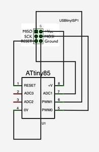
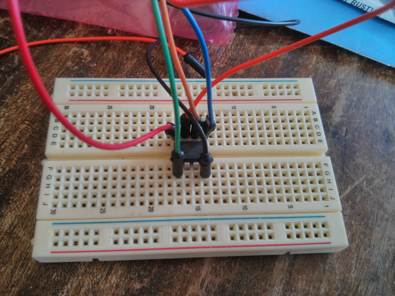
Following this schematic connect the pins from your programmer to the ATTiny on the breadboard.
If you get confused about orientation of your programming cable or microcontroller (like I do), some hints:
ATTiny: look for a dot or bubble, this should be over the RESET pin (1)
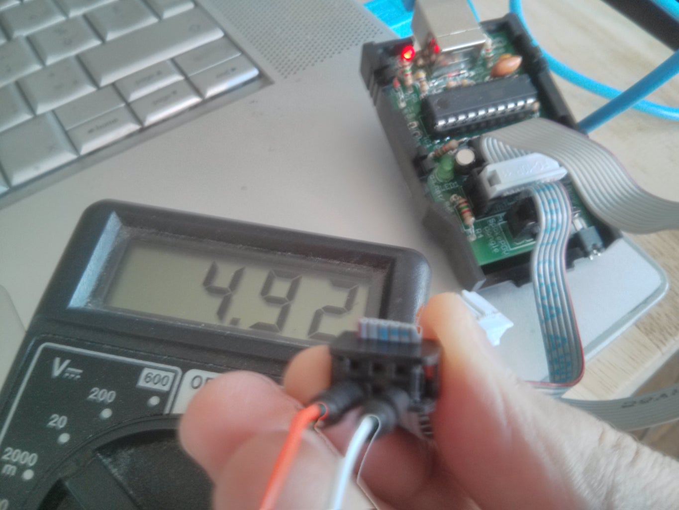
Programmer cable: look for an arrow on the side of the ribbon cable, this is pin 1. Or you can find VCC and Ground via attaching wires and testing with a multimeter.
Schematic CC-BY-SA aurelient / Fritzing
Step 4: Test the Blink Sketch


Connect your programmer and start Arduino.
By default ATTiny runs at 1Mhz. To use the addressable lights, we need to set the fuses to 8Mhz or 16Mhz.
In Tools -> Board, select either
ATTiny85 8Mhz (Internal Oscillator) or ATTiny85 16MHz (Internal PLL), then in Tools choose Burn Bootloader (you'll only have to do this once per chip).
WS2811 pixels work with ATTiny at either speed. 8Mhz is fine for most things and will save you a tiny bit of power. The 16Mhz profile has brown-out detection enabled and will cut out at 4.3V. If you plan to run your lights at less than 5V, always use the 8Mhz profile. Read more about microcontroller fuses and brown-out detection.
Once this is done you can try uploading a sketch to make sure everything works correctly.
Choose Examples -> Basics -> Blink
Change the LED pin from 13 to 4.
Connect a simple LED, the positive end to digital pin 4 on the ATTiny and the negative to ground.
Upload and you should have a blinky LED!
Step 5: Setup Your WS2811 LEDs and Try Your Sketch

Upload your sketch
Connect your programmer and start Arduino
Open Examples -> NeoPixel -> standtest
Change the first parameter to the number of LEDs you have and the second (pin number) to pin 4.
The example below drives 10 LEDs on pin 4, though I was able to drive over 2 meters of high density strip (143 pixels) on one chip :-)
Adafruit_NeoPixel strip = Adafruit_NeoPixel(10, 4, NEO_GRB + NEO_KHZ800);
Setting up your LEDs
If you're using one or two LEDs you probably can test them directly without an external power supply. Connect your LED's GND, 5V pins to 5V, GND on your breadboard.
Place a low value resistor between ATTiny pin 4 and your LED DATA/DIN Pin, this will help with signal integrity (if you want to a more thorough explanation, this post is really informative).
If you're using a strip or more pixels you'll need external power. As above connect ATTiny pin 4 to your strip with a low value resistor.
Connect your power supply's 5V, GND to the LED strip. You'll also need to tie the power supply GND to the GND pin of your ATTiny. See the schematic image for an example setup.
Step 6: Sit Back and Enjoy

Fingers crossed all of these steps worked and you're watching a light show right now! Look for some new Instructables soon with additional projects.
If you have improvements for this tutorial please let me know, I'm sure there are a few things I've missed!
Enjoy your light up creations and happy hacking :-)
If you're looking for some sample code you can give this a try, it is intended to switch between patterns on the tiny with a push button on pin 0!


