

Introduction: Using BlocklyDuino to Create Arduino Sketches - an Easy Intro to the Arduino Uno & C
Hi All...
If any of you have played with MIT's Scratch or Google's Blockly languages, then you will already understand BlocklyDuino. It is a graphic programming language where the "programmer" plugs together various code blocks, operators and values in various combinations to create an Arduino C program. This Arduino C program is then is transferred into the Arduino IDE where the C code can be modified further, compiled, executed and debugged. BlocklyDuino is designed for use with all the various Arduino MCU boards and compatibles, including the Arduino Uno, Arduino Mega2560 and the Arduino Nano. Special code blocks are included to allow you to do digital and analog reads and writes, so your Arduino MCU board can communicate with other component and devices attached to its I/O pins.
In this tutorial I will show you how to write a simple LED "blink" sketch using BlocklyDuino. Then I will show you the resulting C code, and how it can be transferred into the Arduino IDE, where it can then be edited further, compiled, downloaded and debugged. As time allows, I will be adding additional "elementary" level example programs and useful coding tricks. You may come across some examples that are currently being developed. Just come again later and, hopefully, I should have completed that example.
Step 1: Locate a BlocklyDuino Server

The BlocklyDuino graphical development environment is usually accessed through a BlocklyDuino Sever located somewhere out on the Internet. You will either need access to one of these servers, or perhaps download and install a copy from GitHub onto your own local Window PC, Linux PC, or MacBook.
Where to Find BlocklyDuino?
There are several software development groups (individuals, companies, colleges, etc.) that have taken the basic BlocklyDuino language and have developed custom set of code blocks, either extending the capability of the language, or customizing it for their own set of Arduino add-on modules. The following is a partial list of BlocklyDuino Servers where you can go to develop your Arduino C sketches.
1.) BlocklyDuino "General Purpose"
* On the ACSWEB Server at UCSD
2.) BlocklyDuino "Grove Edition"
* On the GitHub Web Server
* On the Mooxell Web Server
3.) Blockly-Duino Enhanced
* On EasyCoding Web Server (Tunisia)
4.) Blockly@duino "French Version"
* On TechMania's WebServer (France) // Set to English (Default was French)
5.) ArduBlockly "ArduBlock Edition"
* From Carlos Perate's ArduBlockly Wiki on GitHub // You download and run this version locally.
[Please excuse the formatting problem above as I could not figure out how to indent the text. The Instructable Editor seems to have the tools for it, but whatever I try, it fails to indent when I come back and view the results.]
The links in the above list will change from time to time, so an Internet search using your favorite search engine using the key word "BlocklyDuino" should provide you with a larger and perhaps more current list where you can explore their implementation of BlocklyDuino in further depth. I prefer to use the "Grove Edition" on the GitHub server for beginning students, and BlocklyDuino Enhanced (BDE) by Adell Kassah on his EasyCoding website for more advanced students.
For ArduBlockly, download the version for your operating system. I use Windows 7, so I downloaded the Windows version, moved the downloaded .zip file to its own folder, and un-zipped it there. It created its own folder tree: .\ardublockly_v0.1.2_windows\ardublockly and there I found the file "ardublockly_run.bat" which is used to launch this version of BlocklyDuino. I have not tested this version extensively, but it appears to run okay and seems to be a pretty nice general purpose implementation.
In the past, and perhaps in the future, there were other versions of Blockly available for running locally. I have an old version of BlocklyDuino-Enhanced which I can still run locally. However, I prefer the ease at which the Server versions run. I think you will, too.
Click on this link to read the GitHub description of BlocklyDuino.
Step 2: The BlocklyDuino GUI (Graphical User Interface)


At this point I assume you have on-hand an Arduino Uno or similar Arduino compatible MCU (Micro-Control Unit) board and that you have found a suitable BlocklyDuino Server with which to work. The basic BlocklyDuino Graphical User Interface (GUI) should look similar to the two photos above. The GUI has three "View Tabs" entitled "Blocks", "Arduino" and "XML". The "Blocks" tab is open by default and it is here that you can place the various graphical code blocks to create your BlocklyDuino program. After creating your BlocklyDuino Program, you can view it translated into the Arduino C language by clicking on the "Arduino" tab. Then there is the "XML" tag which lets you see how the program looks in XML format.
When you want to save your BlocklyDuino code, it will be saved in this XML format. In fact, in the far upper-right side of the BlocklyDuino GUI you should be able to see two buttons entitled "Save XML" and "Load XML". These two buttons allow you to save your current BlocklyDuino code and then later re-load your BlocklyDuino code. Typically, BlocklyDuino will save the code in your default Download directory by default. I usually then move it to an appropriately named BlocklyDuino project folder that I keep on my desktop.
Some implementations of BlocklyDuino also include a "Save Arduino Code" button which will save your program as an Arduino C source file using the ".ino" file type. With both the "Save XML" and "Save Arduino Code" buttons, you will get a pop-up dialog box with which you can name the file to whatever is most meaningful to you. When the file being saved is downloaded to your PC from the BlocklyDuino Server, you will see its name appear in the download status bar area at the bottom of your web browser. When the download is complete you can click on the little up-arrow button and choose "Show in folder" to locate the file in your download folder. You can then cut and paste this file into your project folder for safe keeping (I occasionally clear my downloads folder when I find its taking up too much disk space. Now I have to be more careful.)
The "Upload" button represents one of three ways you can move your Arduino C code from BlocklyDuino into your Arduino IDE (Integrated Development Environment). The second method is to select the whole Arduino C code listing (as shown when you click on the "Arduino" button) and then do a "copy" operation (a right mouse click will reveal a context menu with the various Cut, Copy and Paste operations), then switch into your Arduino IDE and do a "paste" operation, overwriting any code that might already be there. The third way to transfer your Arduino C code to the Arduino IDE is to use the "Save Arduino Code" button to save the current version of your code into your download directory. When its name appears in the download status bar (and after the download has completed), you can simply double click on the filename on the status bar and this will open the Arduino IDE with you Arduino C code. When it does so, you will see a dialog box appear saying something like your Arduino C file needs to be in a "sketch folder" of the same filename. This is just how the Arduino IDE handles sketches (programs). Each sketch (program) has to be stored in a folder named the same as the Arduino C source file. So, just click "OK" and wait a few moments for the Arduino IDE to open with you C code.
Once in the Arduino IDE, you can edit the code as needed (sometimes BlocklyDuino does not generate the most efficient code). You should also take the time to add comments in your Arduino C source code, as BlocklyDuino is not that great for putting comments where you want them. You can then compile the code and "upload" it to your Arduino MCU board where it will be executed. If the program does not work right you can go back and edit it in BlocklyDuino, or here in the Arduino IDE, whichever seems easier. This process of testing the code, then fixing problems is called "debugging" and can be an art into itself. If you are already familiar with Arduino C you may find some of the Arduino C functions are not implemented in your version of BlocklyDuino. One option is to look at the other implementations, as some versions implement functions not implemented in other versions of BlocklyDuino. The other option is to add this functionality from within the Arduino IDE using the Arduino C programming language. Also, many of the Arduino Libraries are not implemented in BlocklyDuino, so to make use of them, that coding will need to be done in the Arduino IDE. But despite these limitations, you'll find you can do most of what students will be using already implemented in BlocklyDuino. If not, try one of the more enhanced versions of BlocklyDuino.
The other two buttons that are commonly found in the BlocklyDuino GUI are the "Discard" and "Reset" buttons. The "Discard" button will remove all the various code blocks from your BlocklyDuino work area so that you can begin programming all over from scratch. The "Reset" button just seems to generate some error message that seems to indicate that it does not work on the BlocklyDuino Server, but maybe it does on a locally run version of BlocklyDuino. I have not tried it, so I can't give much more info on what it does. I never have had to use it.
When working with the BlocklyDuino code blocks, you will need to delete individual blocks from time to time. There are three ways to do this. The first way is to select the block and drag it onto the gray "trash can" icon in the lower right-hand corner of the BlocklyDuino work area. The second way is to select the block and drag it onto the "Blocks" menu area. The third way is to do a right-mouse click on the block and choose "Delete" from the context menu. However, because there are actually two context menus tied to the right mouse click button[Whose great idea was that?!], often times the context menu you want will be covered up by the other context menu you don't want. I believe there is actually a method to this madness, like doing a "right-mouse click-and-hold" to get to the first context menu, and just a "right-mouse click (and release)" to open the second context menu. But I usually mess-up and have to do it a few times before the menu I want presents itself and I can select the command I want. IMHO, I think this is the most poorly designed part of BlocklyDuino.
The other GUI problem I sometimes encounter on some implementations of BlocklyDuino is that when I accidentally click on the "Back" ( <- ) button on the Web Browser, the browser leaves the current page and so the BlocklyDuino Server throws away (i.e. deletes) your entire BlocklyDuino program. If you have not saved your code recently, this can be a very frustrating problem. Also, if you are not careful with the two context menus mentioned above, you can also easily hit the "Back" menu option on the second context menu and this will do the same thing. It seems this was a problem I found on BlocklyDuino Enhanced, but may also occur on other implementations. Fortunately, on the simple "Grove Edition", this is not a problem. By religiously backing up you BlocklyDuino program using "XML Save" as you develop your program you can avoid much of the pain should this problem strike.
I also am using the Google Chrome web browser. I have heard that BlocklyDuino works better on some web browser than on others. So, if your web browser seems to have problems running BlocklyDuino, I recommend using Google Chrome. After all, Google invented "Blockly" which is what BlocklyDuino has evolved out of.
Step 3: The BlocklyDuino "Blocks" Menu
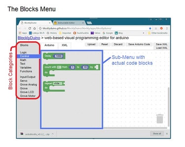
The exact contents of the "Blocks" menu will vary from implementation to implementation. So, as a starter, let's look at the "Grove Edition" implementation. The upper photo shows the "Blocks" menu. Circled in red are the various block categories which contain the actual code blocks. In the photo, we have selected the "Control" category and circled in blue are the 3 available code blocks. The "Delay 1000" code block will invoke the Arduino C delay() function, passing it the value "1000". Since the Arduino C delay() function works with milliseconds, the default value of 1000 will cause the Arduino MCU to wait 1 second before proceeding with the next instruction.
The next code block under the Control category is the "Count with i from 1 to 10 by [ ] / Do" block. In Arduino C, this corresponds with the for() loop. Using the default values, this code block will yield the following Arduino C code:
int i;

void setup()
{

}

void loop()
  {
    for (i = 1; i <= 10; i++) {
      // Some block of code                        // my comment
  }

}
Notice how the "i" variable is initialized as a global variable. This is typical with BlocklyDuino. In C, its considered best to use localvariables whenever possible to keep from wasting memory, a valuable commodity on an Arduino Uno, and most other MCUs. I would prefer to see the code be presented as follows:
void setup() {
}

void loop() {
  for (int i = 1; i <= 10; i++) {
    // Some block of code
  }
}
Here, the integer variable "i" is declared locally within the for() loop. The white space is also a bit "tighter". These changes can be made once you have transferred the C code over to the Arduino IDE.
The third code block under the "Control" category is the "Repeat while / Do" block. This block can also be configured to be a "Repeat until / Do" block by clicking the down arrow next to the word "while". There you will find the other option "until". These two control blocks correspond to the Arduino C While/Do loop (where the test is done at the top of the loop) and the Do/While loop (where the test is done at the bottom of the loop). I think I will hold off on describing the differences between these two loops for now so I can introduce some other code blocks first.
The DigitalWrite Code Block
Under the Input/Output category, you should be able to find a control block called the "DigitalWrite Pin 1 Stat HIGH". As you can guess, this is the code block that corresponds to the Arduino digitalWrite() function call. It also uses the Arduino pinMode() function. Here is the C code that this block produces:
void setup()
{
  pinMode(1, OUTPUT);
}

void loop()
{
  digitalWrite(1, HIGH);

}
The DigitalWrite code block can be configured to use any of the available digital I/O pins on the Arduino MCU. With the Arduino Uno, there are 20 pins that can be configured for digital output: D0 thru D13, and A0 thru A5. Other MCU boards, such as the Arduino Mega, may have many more pins available. At this point, I am not sure (really I am doubtful) if there is a BlocklyDuino Server that supports all the 50+ I/O pins of the Arduino Mega.
Notice that in the BlocklyDuino DigitalWrite code block, they do not allow you to select D0 as this pin is the "RX pin" that the Arduino needs to receive compiled Arduino C code when the code is downloaded from the host PC to the Arduino MCU board. If you were to tie this line to some other device, the Arduino MCU might not be able to receive software updates. Another Digital I/O line that is usually reserved for "system use" is D1, the "TX pin" which is often used by Arduino scripts to send messages to the Serial monitor window in the Arduino IDE. So, it's advisable to never use D0 or D1 for digital I/O pins to interface other devices. The pins A0 thru A5 are usually used for Analog input, but they can be used for Digital I/O as well. So, if you find yourself running a few I/O pins short, these can also be used.
Step 4: Your First BlocklyDuino Program


For my first program example, I want the reproduce the Arduino demo sketch called Blink.ino. If you have used Arduino before, you should recognize this script as the most basic demo script. It simply outputs a HIGH value to a pin (usually D13), waits a second, then outputs a LOW value to the same pin and waits another second before looping back around repeating this code ad infinitum.
1.) Select the "DigitalWrite" code block from the "Input / Output" category and drag it into the BlocklyDuino work-space (the area indicated by the 2D matrix of light gray dots). Repeat this as we will need two copies of this block.
2.) Go to the "Control" category of blocks and select the "Delay 1000" code block. Drag it into the work-space as well. Repeat this as we'll also need two copies of the Delay block. At this point we should have 4 code blocks randomly placed in our work-space.
3.) Drag one of the DigitalWrite code blocks to the upper left corner of the work-space. Select I/O pin 5 and make sure the value it will be set to is "HIGH".
4.) Drag one of the two Delay 1000 blocks and align it under the first DigitalWrite block so that the two "snap" together.
5.) Take the second DigitalWrite code block and drag it under the first two blocks that we have just snapped together. This third code block should snap together in the same way.
6.) On this second DigitalWrite code block, set the I/O pin setting to 5 and set value block to "LOW".
7.) Now take the second Delay 1000 block and snap it into place under the first three code blocks.
You should now have four code blocks plugged together as was shown in an earlier photos include with this write-up. If you now click on the "Arduino" button, you should see the following C code:
void setup()
{
  pinMode(5, OUTPUT);

}

void loop()
{
  digitalWrite(5, HIGH);
  delay(1000);
  digitalWrite(5, LOW);
  delay(1000);

}
In order to test this code, you will need to take an LED and a (current limiting) resistor (in the range of 220 to 1K ohms) and plug them into a breadboard such that the short lead (wire) of the LED goes to one side of the resistor. The second side of the resistor needs to be jumpered to one of the GND pins on the Arduino MCU board. A second jumper will be required to connect the long lead of the LED to the D5 input pin. [As a test to make sure your LED is wired properly, you can touch the jumper wire that should go to D5 to the +5V pin. Assuming your Arduino MCU board is powered up (i.e. connected to your host computer via the USB cable), the red LED should light up.]
I have included a photo of my Arduino Uno with this LED and resistor setup. To test the code, we'll need to transfer the Arduino C code from the BlocklyDuino Server to the Arduino IDE running on your Windows PC (or Linux PC or MacBook, whatever you're using). If all else fails you can always copy & paste the code into the Arduino IDE, overwriting any code that may be there. The result should look like my Arduino IDE photo above.
To compile, just click on the "Upload" button (the circle button with a right pointing black arrow). It will likely ask you to save your file, so name it anything that makes sense to you, and click on the Save button. Once saved, the compilation will begin, and then the actual "Upload". As it uploads, you should see a lot of blinking on the RX LED on the Arduino board. When finished, you should see the LED you have attached to I/O pin D5 begin to blink... on for one second, then off for one second, and looping around to blink the LED forever (or at least till you either power down the MCU or upload a different sketch).
Step 5: Modifying Your BlocklyDuino Program
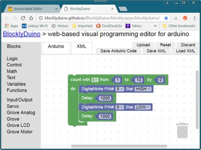
Now, let's say we only wanted to have the LED blink just 10 times. This can be accomplished by surrounding the code in the main loop() function with a for() loop in Arduino C, or by using the "Count with i from 1 to 10 by [ ] / Do" block located in the Control category of code blocks. Drag this block out into the middle of your work area. Then "grab" the four code blocks that was our earlier LED blink program and drag it them over into the "Do" part of the "Count with i from 1 to 10 by [ ] / Do" control block. These 4 blocks should snap into place when positioned properly. See the photo above to see how they should now look.
Now to complete the control block, select the "0" value block from the Math category and drag it into your work area. Click on the "0" in the middle of this little block and change it to "1". Now snap it into place just to the right of the "by" word in the "Count with i from 1 to 10 by[] / Do" block. This value controls the increment value of the loop, but if you should forget to include it, then BlocklyDuino will assume the increment value is "1".
Now click on the "Save XML" button to save your new program. Name it something meaningful like "Blink_10_times". Next, click on the "Arduino" button to see the resulting Arduino C code:
int i;

void setup()
{
  pinMode(5, OUTPUT);
}

void loop()
{
  for (i = 1; i <= 10; i++) {
    digitalWrite(5, HIGH);
    delay(1000);
    digitalWrite(5, LOW);
    delay(1000);
  }

}
If you now transfer this file from BlocklyDuino into the Arduino IDE, you can save, compile and upload the code to your Arduino Uno as you did in the previous example. Again, look at the RX LED on the Arduino MCU board. As the compiled code is being uploaded, it should blink on and off wildly. When this stops, look at the LED that you had connected to the I/O pin D5. It should now blink just 10 times. Job done!
From this point, I would suggest that you just play around with the various other instructions, making small BlocklyDuino code changes, then examine the resulting Arduino C code. Transfer the more interesting programs over to the Arduino IDE and test them out. Then, do a search on the Internet using Google, or some other search engine, and look for "Arduino Uno Tutorials". Most of the elementary ones can be done with BlocklyDuino, or BlocklyDuino Enhanced.
Step 6: Using the Arduino Serial Monitor
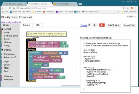
One aspect of Arduino C programming that is a bit different and is quite useful to know is how to communicate between your Arduino C program and the Arduino Serial Monitor window. This serial communication method uses the Arduino digital I/O pins D0 (RX) and D1 (TX). Arduino C has a built-in "class" (think of a class as a specialized data type with its own collection of functions) called "Serial" which has a number of member functions which you can use to print text, integers and floating point numbers to the Serial Monitor window, and to read characters from the Serial Monitor keyboard input text box. As I assume you are new to C, I present this topic using the set of BlockyDuino Serial Monitor code blocks that come with BlocklyDuino-Enhanced. Other implementations of BlocklyDuino come with more limited Serial print capabilities. For instance, the "Grove Edition" has just the 'Serial print[" "]' function in the Input/Output blocks category. The BlocklyDuino-Enhance implementation comes with 9 different code blocks, including two used to read-in characters from the Serial Monitor's keyboard interface.
A.) Outputting Characters to the Arduino Serial Monitor
In the Block menu of BlocklyDuino-Enhanced, under the "Serial" category, you will find 9 different code blocks. Locate the one called "Print on new line" and drag it into your work space. Now click on the "Arduino" button to view the equivalent Arduino C code:
<code>

void setup() {
  Serial.begin(9600);
}


void loop() {
    Serial.println("");
}

</code>
[I apologize for the buggy Instructable Editor (and Viewer?) which keeps inserting HTML code into my Arduino C listings. To keep this from happening, I've inserted HTML and tags around my Arduino C code. I'm hoping that it will fix the problem. So, just ignore the and tags that surrounds my Arduino C code. :-( ]
As shown above, to invoke the Serial console, you must first use the "Serial.begin(9600);" instruction which initializes the Serial monitor object and sets the data transfer rate to 9600 baud. Once that is done, you can use the 'Serial.println(" ");' instruction to print a string of characters, a single character, an integer value or a floating point value. For a string, just insert the characters you want to print between the two quotes. In BlocklyDuino, this is usually done with the string block (the one that has two double quotes with a space between it). This string block is normally included as a part of the "Print on new line" code block. So just enter your characters between those two quotes. If I want to say "Hello, World", just put these characters in between the two double quotes. Then click on "Arduino" and the code should be:
<code>

void setup() {
  Serial.begin(9600);
}

void loop() {
  Serial.println("Hello, World");

}


</code>
Once this program is transferred into the Arduino IDE, compiled, uploaded and executed, you can click on the "Serial Monitor" button (the one that looks like a magnifying glass) in the upper right corner of the Arduino IDE. This will open a window where you should be able to view the "Hello, World" message. Press the reset button on your Arduino MCU board to see the message appear again.
In the "Serial" category of control blocks, there is another one called "Print on same line", which functions like the "Print on new line" except for the fact that it does not generate a newline (CR/LF) at the end of the message string. This is good for stringing together multiple messages on the same line of the Serial console display.
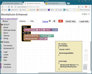
To display a single character, either enclose the character with a pair of single quotes, or use a variable of type "char". To display an integer, a long (long integer) or a float (floating point number), create a new variable of the desired type, assign it a value (or calculate a value) and the use the name of the variable in place of the string. Make sure there are no quotes around your variable names or values, or they will be treated as strings.
Take a close look at the example in the photo above (left). I created an integer variable called "myVar" and assigned it a value of "2017". Then I used the "Print on same line" code block (i.e. Serial.print() in Arduino C) to display a label: "MyVar = ". Then I used the "Print on new line" code block (i.e. Serial.println() in Arduino C) to display the value of myVar (2017). If you compile and upload this example, you should get the message "MyVar = 2017" on the same line in the Serial Monitor window.
B.) Inputting Characters from the Arduino Serial Monitor
In the "Serial" category of code blocks, there are two others called "Serial Available?" and "Serial Read". These two code blocks can be used to read characters entered via the Serial Monitor and your PC's keyboard. This allows you to enter information and pass it to your sketch (program) running on your Arduino MCU. The Serial Monitor window includes a text-box along the top of the window which you can use to enter from 1 to 64 characters (the maximum buffer size) . Then you can click on the "Send" button and the Arduino IDE will upload these characters to the Arduino MCU which will buffer the characters until your sketch has had a chance to read them in.
In your BlocklyDuino program, you must use the "Serial Available?" code block within a "Repeat While / Do" loop block. The Repeat While / Do code block translates into the Arduino "C" While/Do block. The Repeat While / Do code block also must be used with a "[ ] = [ ]" logic block. I modified this Logic block to read "[Serial Available?] > [0]" and then plugged this into the While part of the Repeat While / Do block. The value returned by Serial Available? is the number of characters in the input buffer. So, if there is keyboard data in the input buffer, Serial Available? should return a number greater than zero. When this happens, you can use the Serial Read block to read in the character. Since the data is being read in a character at a time, and our program prefers they be a string, I have to build my string using this Repeat While / Do loop. First, I create a String variable (myString) and then use the "myString Concat [ ]" code block within the "Do" part of my Repeat While / Do loop. Be sure to use the String category's "Declare i as String Value" code block to create your myString variable, as this will then allow you to see eight more String code blocks that you don't get when you create your variable with the Variable's category's "Declare i as long Value" code block to create your myString variable and then set the data type to String. Again, be sure to use the String category's "Declare i as String Value" code block to create myString.
Here's the Arduino C code produced:
<code>char myChar;
String myString; void setup() { myChar = ' ';myString = "";
Serial.begin(9600);
// Serial.begin(9600); // Delete or comment-out this duplicate line.
}
void loop() { while ((Serial.available() > 0)){ myChar = Serial.read(); myString.concat(myChar); delay(10);
}
if (myString != "") { Serial.println(myString); myString = "";
}
}
</code>
For some reason, I could not get the String concatenation function (".concat()" ) to work right without the "delay(10)" line inserted into the code. Also, look out for the duplicate "Serial.begin(9600);" line in the Arduino C code which should be deleted. Try out the above sketch to get a better idea how it works.
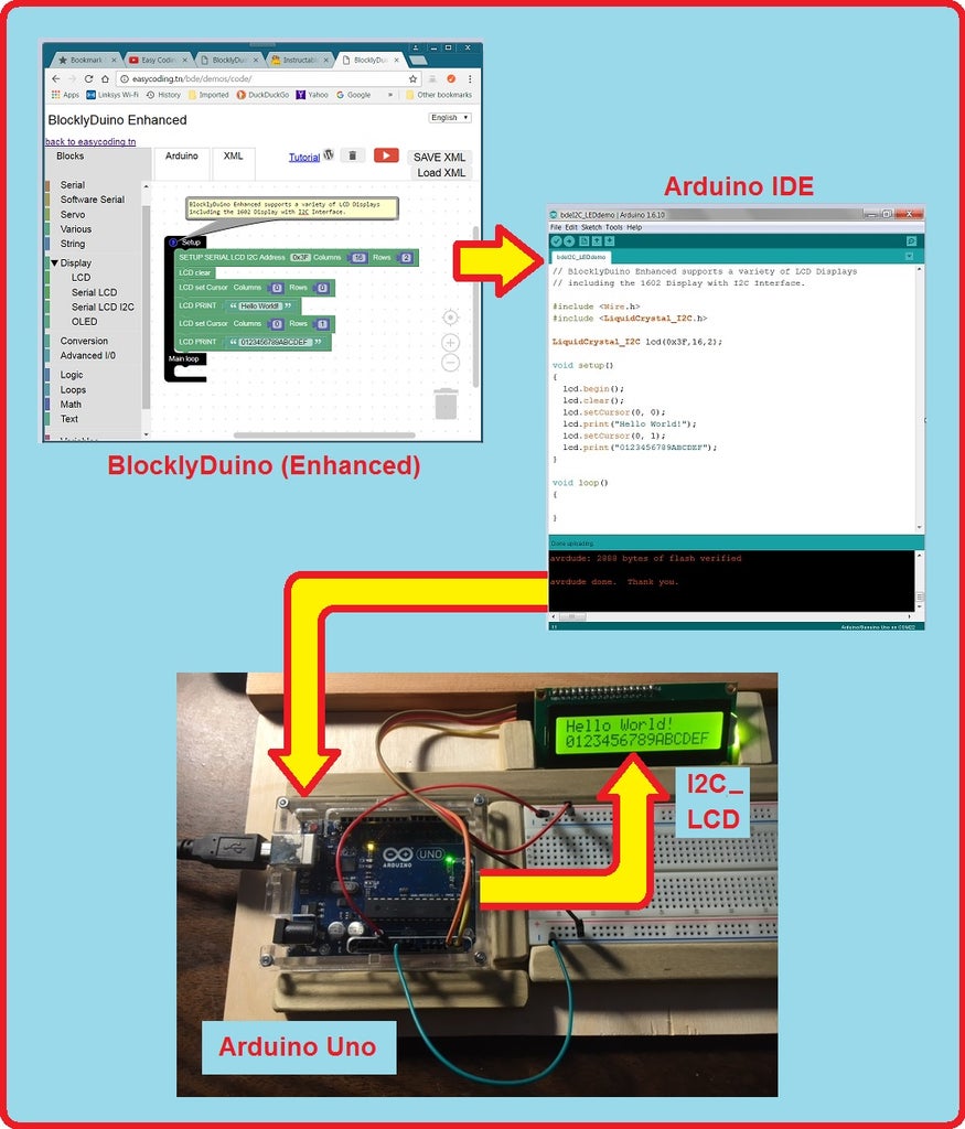
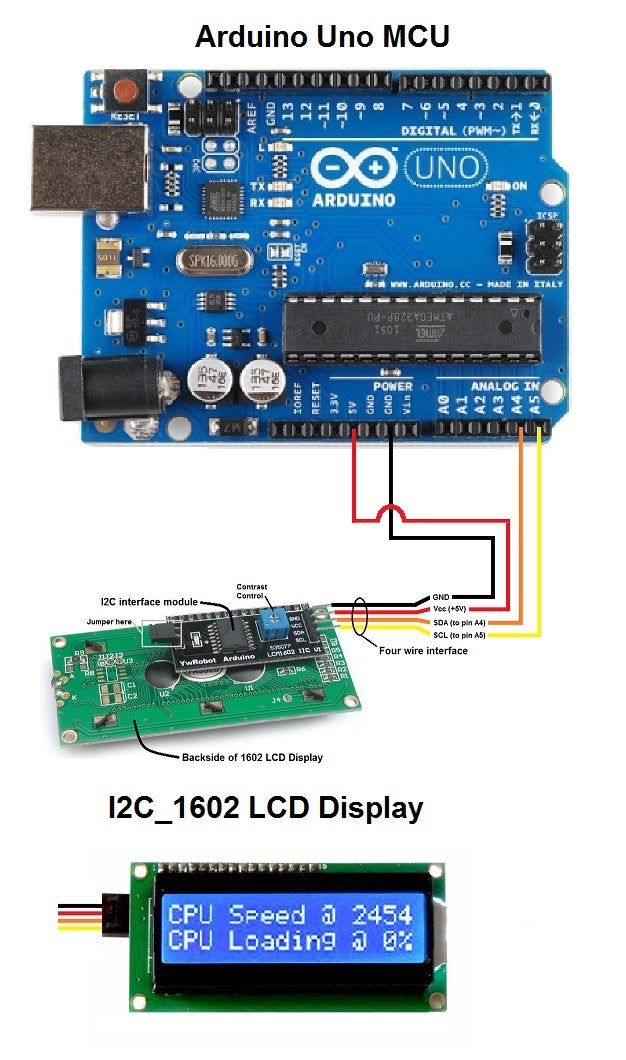
Step 7: Using an I2C 1602 or 2004 LCD Display
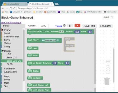
I2C LCD Display Support
BlocklyDuino-Enhanced includes support for several LCD and OLED display devices, including two of my favorites, the I2C_1602 LCD Display and the I2C_2004 LCD Display. I prefer the I2C version of the 1602 and 2004 LCDs as the I2C interface uses only two I/O pins instead of maybe 6 pins for the default 4-bit parallel version of these LCD displays. The extra cost is not that much more, and I2C makes the device much easier to set up. The I2C interface comes in the form of a small "daughter board" that is soldered onto the back side of the 1602 or 2004LCD modules. Typically, when you buy a 1602 or 2004LCD you will either have to solder on a 1 x 16 pin set of header pins, or the I2C interface module which uses the same 16-pin "connector". So, soldering will usually be required whether you go for the default 4-bit parallel interface or the I2C interface. However, if you shop around carefully enough, you may find a few vendors who do offer the I2C_1602 interface pre-installed (already soldered into place), but you will likely have to pay more money.
The difference between the 1602LCD and 2004 LCD is the size of the display. The smaller 1602 LCD displays two lines with 16 characters per line. The larger 2004LCD displays 4 lines with 20 character per line. The BlocklyDuino-Enhance code blocks supports both versions -- you just have to specify the number of "columns" (i.e. characters per line) and "rows" (i.e. number lines per display). You will also have to specify something known as the "I2C address"which usually will be either "0x3F" or "0x27". Both of these numbers are Arduino C formatted hexadecimal values.
The second photo above also shows how to connect the I2C LCD to the Arduino Uno using the I2C interface. This "2- wire" interface (not counting +5V DC power and GND wires) has two signal lines called "SDA" and "SCL". The SDA (Serial DAta) line should be routed to Arduino pin A4 while the SCL (Serial CLock) line should be wired to Arduino pin A5. With the Arduino Uno, the A4 and A5 pins are commonly used for the I2C interface. On other boards like the Arduino Mega2560 these 2 signals will likely be routed to other pins. So, double check the documentation that comes with your MCU board to verify that A4 and A5 can be used for the I2C SDA and SCL signal lines, or which pins to use in their place. If you have to substitute in other pins, do this in the Arduino C code as the BlocklyDuino code blocks assume A4 and A5.
As the I2C interface uses a special protocol, you will need to use a special Arduino Library called Arduino_I2C. The default Arduino LiquidCrystal library only supports the 1602- and 2004-LCD displays in 8-bit or 4-bit parallel modes. EasyCoding has a link to the version of Arduino LiquidCrystal_I2C library which works well with their BlocklyDuino-Enhanced Serial I2C LCD code blocks. The direct link to download the library is:
http://easycoding.tn/wp-content/uploads/2016/12/A...
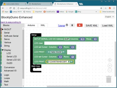
Here I am assuming you are using Windows on your PC. This LiquidCrystal_I2c will need to be downloaded, unzipped and moved into the "Arduino libraries" folder (which with Windows is normally "C:\Program Files (x86)\Arduino\libraries". When you download the directory, it will be downloaded into your default Downloads directory. At this point you should create a new directory (folder) and move this .zip file into the new folder. Within this new folder, unzip the file. This will produce yet another sub-directory with a different file name. You will need to rename this new sub-directory to "LiquidCrystal_I2C" and then copy it (and its contents) into the Arduino libraries directory (the path of which is shown at the top of this paragraph). Once the LiquindCrystal_I2C distribution file has been un-zipped, the sub-directory renamed to "LiquidCrystal_I2C" and moved into the Arduino libraries folder, you will need to close and restart all your Arduino IDE sessions. After the Arduino IDE restarts, it will know about the new change to the Arduino libraries. You can then try to reproduce the BlocklyDuino I2C LCD programs shown in the third photo (above).
The third photo above shows a short BlocklyDuino Enhanced program that generates the Arduino C code necessary to display the message "Hello, World!" on a 1602 LCD display along with a second line that displays hex numbers between 0 and F. If you examine this photo closely, you will see it uses a series of six LCD code blocks within the setup() part of the program (since I only want to run it once). The first code block is labeled "Setup Serial I2C Address[0x3F], Columns[16], Rows[2]". This code block allows you to create your LCD object and it allows you to specify the I2C Address, the number of columns (characters) and rows (lines) it can handle. By default, this block is set up for most I2C_1602 LCDs. However, if this does not work for you, I recommend changing the I2C address from 0x3F to 0x27 as these are the two most commonly used I2C addresses; the only two I have ever seen used. To use this with an I2C_2004 LCD, you will likely have to change the I2C Address (the four I have are all 0x27, as some of my I2C_1602 LCDs are), and then set "Columns" to 20 and "Rows" to 4.
After creating your LCD object, it's a good idea to clear the display as on occasion they will come up with "garbage" on the display. This is done with the "LCD Clear" code block and it will leave the cursor (where the next character will be displayed) set to position Column 0, Row 0. Often times you will find that you need to re-position the cursor. This is done by using the "LCD Set Cursor Column[ ] Row[ ]" code block. Then to display some characters, you use the "LCD Print ["Hello, World!"]" code block. Be sure to change the "Hello, World!" text to what-ever message you want to display. Here is a listing of the Arduino C code produced:
<code>#include "Wire.h"
#include "LiquidCrystal_I2C.h"LiquidCrystal_I2C lcd(0x3F,16,2);
void setup() {
lcd.begin(); lcd.clear(); lcd.setCursor(0, 0); lcd.print("Hello World!"); lcd.setCursor(0, 1); lcd.print("0123456789ABCDEF"); }void loop() { // do nothing }
</code>
The neat thing about these LCD displays is that you can use them in place of the Serial Monitor window of the Arduino IDE so that your Arduino project can be packed so that it runs independently of your development PC (i.e. the PC you use to run the Arduino IDE).
Step 8: Final Thoughts
Additional BlocklyDuino Examples
I think on future examples, I will only supply photos of the BlocklyDuino code used with a listing of the "cleaned up" Arduino "C" Code, and perhaps a description of the circuit. Trying to explain things in detail using English is rather tedious, and hopefully you understand enough now that you can piece together these examples with minimal English description.
BlocklyDuino -- A Great STEM Teaching Tool for Middle & High Schools
IMHO, BlocklyDuino is a great STEM (Science, Technology, Engineering, Math) teaching tool for introducing middle- and high-school students to the Arduino Uno and "C" programming in general. It's a great bridge between Scratch and Arduino C because it allows students to view the various coding blocks as Arduino C code, so they can begin to understand how "C" and Arduino programming works. The many introductory level Arduino tutorials that you can find on the Internet can be easily adapted to class projects and implemented in BlocklyDuino, and later enhanced in Arduino C.
TUNIOT -- BlocklyDuino for the NodeMCU / ESP8266 WiFi SoC
EasyCoding also offers "TUNIOT", a special customized version of BlocklyDuino language designed for use with the NodeMCU, an ESP8266 WiFi SoC based, "breadboard friendly" MCU board. TUNIOT includes code blocks for logging into a WiFI network, as well as code blocks for developing both server and client IoT (Internet of Things) applications. TUNIOT is described in a series of tutorial videos on YouTube and I plan to add additional Indestructible articles in the near future on both BlocklyDuino and TUNIOT.
TUNIOT LINKS:
TUNIOT Server URL:
http: //easycoding.tn/tuniot/demos/code/
TUNIOT Tutorial Videos:
https: //www.youtube.com/playlist?list=PLfPtpZzK2Z_Qy2ZbbzvWa58cKKOisMUZ1
[ Note: be sure to remove the space (" ") between "https:" and "// etc." in the 2 URL above. ]


