

Introduction: VHDL Stopwatch

This is a tutorial on how to program a stopwatch using VHDL and a Basys3 Atrix-7 Board. The stopwatch uses four buttons—Start/Stop, Reset, Save Lap, and Display Lap— and is able to count from 00.00s to 99.99s. The time is displayed on the Basys3's seven segment display. We created three VHDL files that acquire two clock speeds, manage anode and cathode displays, and set button controls.
Step 1: Hardware/Software
1. Basys3 Atrix-7 FPGA Board
2. USB 2.0 A Male to Micro-B Male
3. Vivado Design Suite from Xilinx
Step 2: Black Box Diagram

Before writing the code, you should be familiar with the overall design of the program. The stopwatch is broken down into two sub parts. The "Clock Divider" takes the Basys3's 100MHz clock and creates two smaller 240Hz ("Refresh Clock") and 100Hz ("ClockDig1") clocks. Those two clocks are then used by the "Display" sub part. "Display" then outputs the correct display based on time and buttons pressed.
Step 3: Stopwatch Design File
This file creates the main inputs and outputs along with the two sub parts. You will need to connect all of the inputs and outputs to their correct ports so that the circuit functions properly. The initial clock input "CLK" (which is the Basys3's internal 100MHz clock) will be connected to the "Clock Divider." The "Clock Divider" will then send the "Refresh Clock" and "ClockDig1" clocks to the "Display" sub part. Lastly, "Display" will utilize those two clocks along with all four buttons in order to generate the "Anode" and "Cathode" outputs.
This file should use two signals (connecting the two "Clock Divider" outputs to "Display" and two components ("Clock Divider" and "Display").
Attachments

Step 4: Clock Divider
In order to create the 240Hz and 100Hz clocks, we need to create two counters that will increment every time the 100Hz clock hits a rising edge. One counter will have to count to 208,334 (240Hz) and 500,000 (100Hz). Once they reach those values, then another two variables will have to go HIGH to create the clocks. At the end of the process, "ClockDig1" and "Refresh Clock" are set equal to their respective variable.
Attachments
Step 5: Display
This sub part performs the most functions in our circuit. To start, make sure all the input and output ports are correct; remember that this will intake the outputs from "Clock Divider" and will also include the buttons. This file is includes three process blocks : button functions, anode/cathode display, and button clocks.
Button Functions: This process block dictates what happens when a certain button or combination of buttons are pushed. It also sets the numbers that will be displayed on the seven segment display by using the "ClockDig1" clock. This block requires many integer signals to keep track of display values.
Anode/Cathode Display: This process block sets the display. When the block receives the numbers to be used from the Button Functions block, it will then display them on their respective anodes. The "Refresh Clock" allows the seven segment display to show different values "at once."
Button Clocks: Using "ClockDig1," this process block detects edges for buttons 3 (Display Lap), 2 (Save Lap), and 0 (Start/Stop). The program is able to detect when a button is pushed and then save it to a signal where it is utilized in the previous process blocks. There are a lot of different signals that are used for this process so it is difficult to keep track of what they do; name them based on their function to make things easier to keep track of.
Attachments
Step 6: Constraints

This file simply routes the program's inputs and outputs to the necessary components on the Basys3 board. This program uses just four buttons, the 100Mhz clock, and four anodes (along with each of their eight cathodes). For reference, use the user manual linked below.
https://reference.digilentinc.com/_media/basys3:basys3_rm.pdf
Attachments
Step 7: DONE!
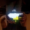
Push the Start button and watch the display go into action! Keep track of laps and then reset the timer when you need to.
Some additional ideas to build from this:
1. Add a speaker that makes a unique noise for each button being pushed
2. Add an actual clock that can also differentiate between AM and PM


