

Introduction: WS2812B LED Cube 96 for Arduino Magic Colorful


Hey,guys,this is the Fourth time we(smart prototyping) post an instructable here,
thanks for watching! We will keep on posting funny instructables. This is a LED magic cube,we hope it be helpful for you and we'd love to communicate with you guys!
Before making the Cube,let's have a overview:
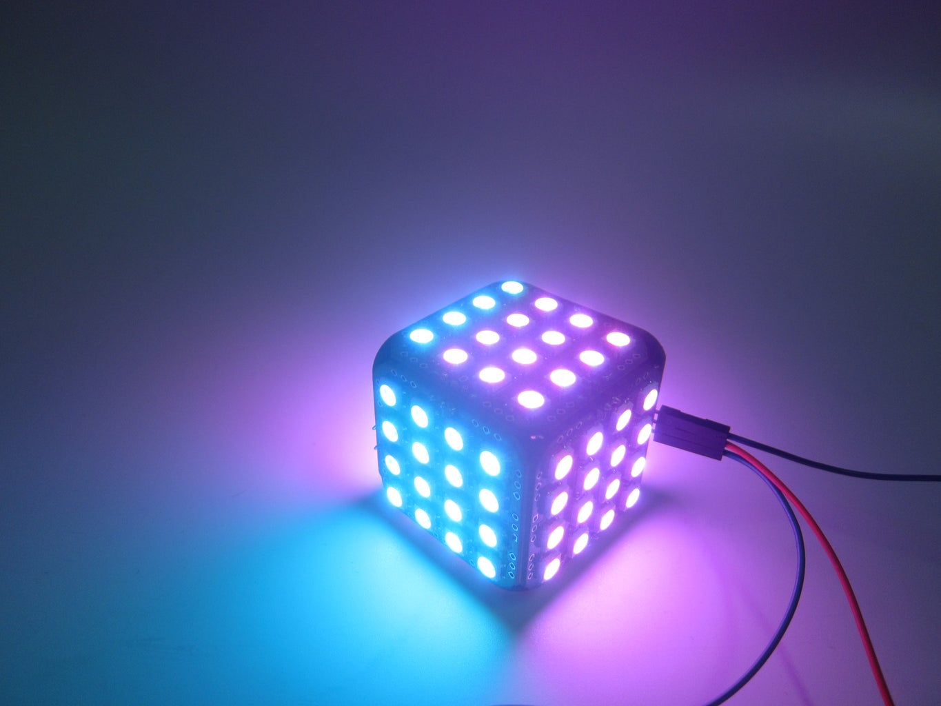
This Cube was made by six 4x4 LED matrix board, LED light is WS2812B.What's amazing, it’s not just a Cube, you can control every LED light’s brightness on it by using a Arduino and GND/VCC/Single three port! In addition, the power supply should be 5V,600mA.If you use computer USB power suppply,you need to low down the brightness in code,because the computer USB ports is 500mA.
There are 16pcs WS2812B LED light, two input ports and two output ports on the WS2812B LED board unit.With the four ports, you can easily build a 3D structure, for example, a cube.
So how to control the LED,All the LED light’s signal on the unit boards are serial connected, and controlled by one-line protocol(the maximum quantity is 1024pcs LED light).You can freely control every single LED’s color, each pixel of the three primary color can achieve 256 brightness display, completed 16777216 full color display, and scan frequency not less than 400Hz/s.
Here is our product page
tinde:
WS2812B LED Cube 96 for arduino magic colorful
smart-prototyping
Step 1: Determine the Connection Rules
Because every unit LED matrix’s signal are serial connected, and controlled by one-line protocol, you can treat the unit board as a big LED light, just make sure all the units follow the in/out rule, then you can easily control all the units and any single LED lights on the whole structure. To fix the units,we solder it with 2.54mm male headers,of course,you can use other methods.There are eight GND 1x3pin 2.5mm holes, you can solder them freely for constructing purpose .For general structure connecting purpose, you can solder either female headers or male headers.However,you should solder male header on these ports for construction purpose.
Step 2: Solding the Header(2.54mm),Connecting the Board2 and Board3


Now let's start to make it!
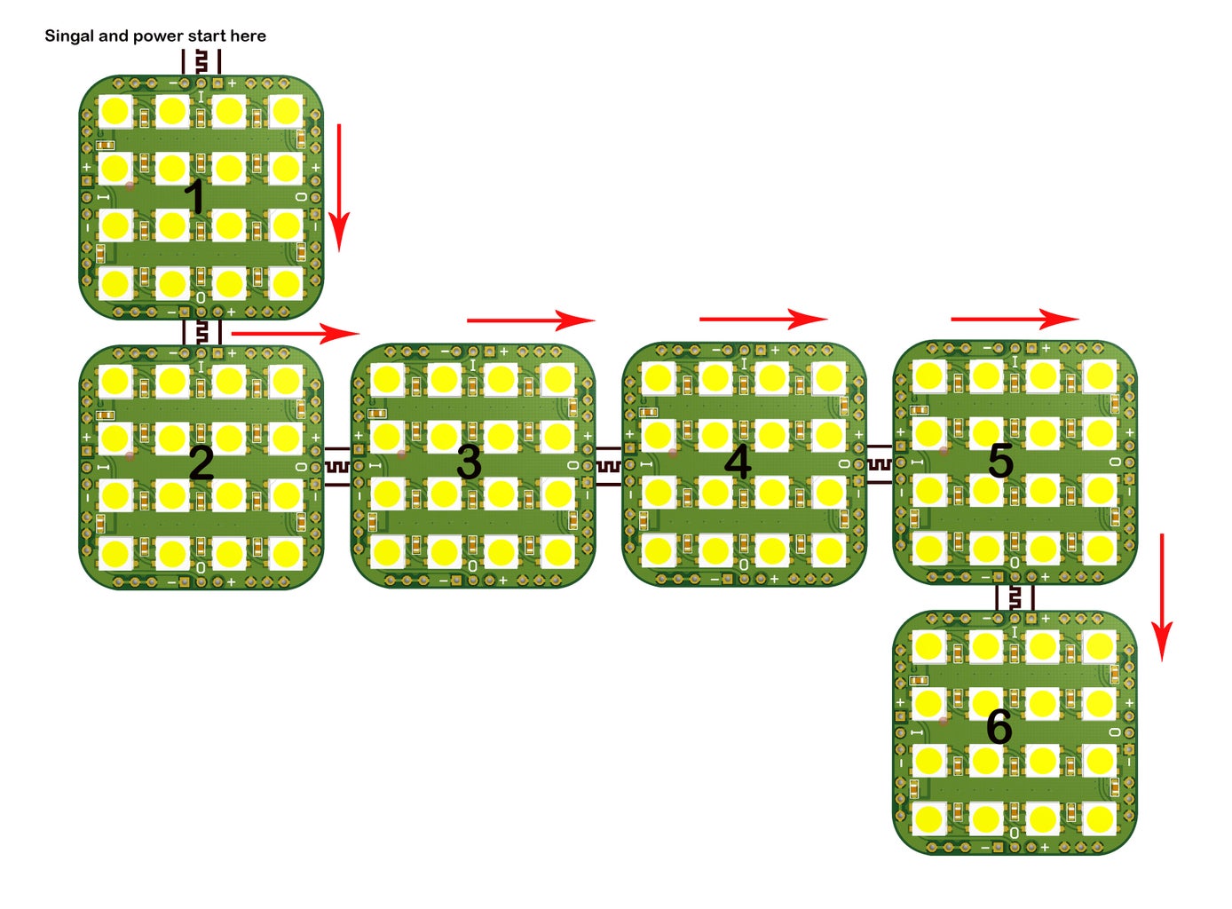
In order to make it more simple to understand,we numbered all the boards.
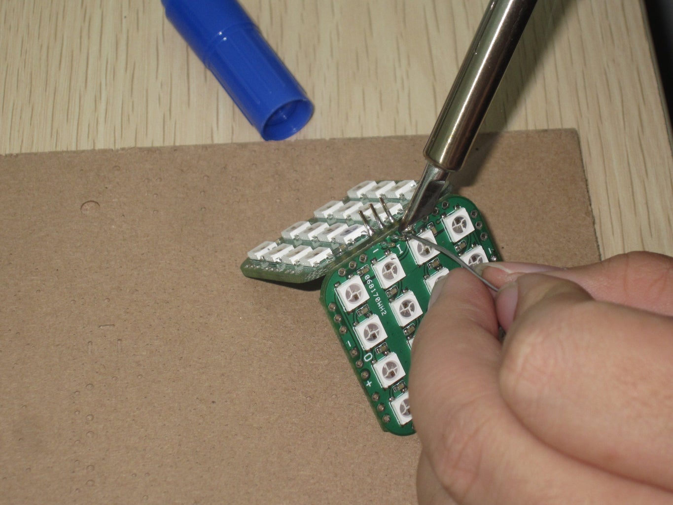
The tools you may needed:soldering machine,male headers and pliers.
Connecting the board2 and board3:putting the two sides of male header inset in the "in" ports (the holes with the" I " marking) and "out" ports (the holes with the" O" marking) respectively on the board2 and board3.
Attention:you need to dislodge the plastic on the male header.
Detail please refer to the pictures.
Step 3: Connect the Board2, Board3,board4,board5


You can use the same method to connect the board3 with board 4 and board 4 with board5.
Attention:you shoud not connect the board2 and board 5 with "in" port and "out" port,instead,you can connect them by jointing any two(1x3pin 2.5mm holes)corresponding GND holds respectively on the two board.
Step 4: Connect the Board1 and Board6


At the Step1,you have seen a picture showing you how to connect the board 1 and board 6,in order to make sure the structure more firmly,you can soldering the GND as well.
So far,a LED cube is finished.Here comes the most exciting moment! Just switching on the power,you will witness the beautuful shining Cube made by yourself shining as you wanted.
Step 5: Download the Code
Download the code
https://github.com/adafruit/Adafruit_NeoPixel
Adafruit_NeoPixel strip = Adafruit_NeoPixel(60, PIN, NEO_GRB + NEO_KHZ800);
Change the number of LED lights.


