

Introduction: Wall Following Robot / Obstacle Avoiding Robot


Fully autonomous and intelligent machines can minimize human liability and extend automation to fields like civil services and defense. AI researchers are attempting to automate services like firefighting, medical care, disaster management, and lifesaving duties through autonomous robotic vehicles. One challenge that these vehicles must overcome is how to successfully detect and avoid obstacles such as rubble, fire, pitfalls, etc.
In this Instructable we will show how to create an autonomous wall following robot (vehicle) using a few external ultrasonic and infrared (IR) sensors and Silego GreenPAK.
Required Materials
Hardware:
1. An ultrasonic sensor;
2. Silego GreenPAKSLG46620V chip
3. A pair of IR obstacle detection sensors
4. Motor driver circuit (L298N)
5. Four DC motors
6. Wheels and a 4-wheel drive car skeleton
Software:
1. Silego GreenPAK designer. http://www.silego.com/softdoc/software.html
A digital output pin of the GreenPAK controller is used to trigger the ultrasonic sensor (aka sonar), and a digital input pin is used to collect the resultant echo from the obstacles ahead for analysis. The output of the IR obstacle detection sensor is also observed. After applying a set of conditions, if an obstacle is too near, the motors (connected to each of the 4 wheels) are adjusted to avoid the collision.
How it is working?
The wall following robot must be capable of detecting and avoiding obstacles. The design of such a robot requires the integration of different sensors, such as bump sensors, infrared sensors, ultrasonic sensors, etc. By mounting these sensors on the robot, it can get information about the surrounding area. An ultrasonic sensor is suitable for obstacle detection for a slow-moving autonomous robot, as it has a low cost and relatively high range.
An ultrasonic sensor detects objects by emitting a short ultrasonic burst, and then listening for the echo. Under the control of a host microcontroller, the sensor emits a short 40 kHz pulse. This pulse travels through the air until it hits an object, and then is reflected back to the sensor. The sensor provides an output signal to the host that terminates when the echo is detected. This way, the width of the returned pulse is used to calculate the distance to the object.
This wall following robotic vehicle uses an ultrasonic sensor to detect objects in its path. The motors are connected through a motor driver IC to the GreenPAK. The ultrasonic sensor is attached to the front of the robot, and the two IR obstacle detection sensors are attached on left and right sides of the robot to detect side obstacles.
As the robot moves on the desired path, the ultrasonic sensor continuously transmits ultrasonic waves. Whenever a wall (or obstacle) is in front of the robot, the ultrasonic waves are reflected back from the wall, and that information is passed to the GreenPAK. Simultaneously, the IR sensors are emitting and receiving IR waves. After interpreting the inputs from the ultrasonic and IR sensors, the GreenPAK controls the motors for each of the four wheels.
Step 1: Algorithm Description
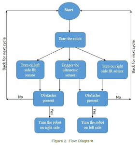
At startup, the four motors are turned on simultaneously, causing the robot to move forward. Next, the ultrasonic sensor sends out pulses from the front of the robot at regular intervals. If an obstacle is present, the sound pulses are reflected and are detected by the sensor. The reflection of pulses depends upon the physical state of the obstacle: if it is irregular in shape, then the pulses reflected will be fewer; if it is uniform, then most of the transmitted pulses will be reflected. The reflection also depends upon the direction of the obstacle. If it is slightly tilted, or placed in parallel with the sensor, then most of the sound waves will pass unreflected.
When an obstacle is detected in front of the robot, then the side outputs from the IR sensors are observed. If an obstacle is detected on the right side, the left side tires of the robot are disabled, causing it to turn towards the left, and vice versa. If an obstacle is not detected, then the algorithm is repeated. The flow diagram is shown on the Figure 2.
Step 2: Ultrasonic Sensor HC-SR04


An ultrasonic sensor is a device that can measure the distance to an object by using sound waves. It measures distance by sending out a sound wave at a specific frequency and listening for that sound wave to bounce back. By recording the elapsed time between the sound wave being generated and the sound wave bouncing back, it is possible to calculate the distance between the sonar sensor and the object. Sound travels through air at about 344 m/s (1129 ft/s), so you can calculate the distance to the object using this formula:
0,5*(344*m/s*[reflection time])=distance
The HC-SR04 ultrasonic sensor consists of four pins: Vdd, GND, Trigger, and Echo. Whenever a pulse from the controller is applied to the Trigger pin, the sensor emits an ultrasound wave from a “speaker.” Reflected waves are detected by the “receiver,” and are transmitted back to the controller via the Echo pin. The longer the distance between the sensor and an obstacle, the longer the pulse at the Echo pin will be. The pulse remains on for the time it takes the sonar pulse to travel from the sensor and return back, divided by two. When the sonar is triggered, an internal timer starts and continues until the reflected wave is detected. This time is then divided by two, because the actual time it took the sound wave to reach the obstacle was half the time that the timer was on.
In order to generate the ultrasonic pulse, you need to set the Trigger to a HIGH state for 10µs. That will send out an 8-cycle sonic burst, which will reflect off of any obstacle in front of the device and be received by the sensor. The Echo pin will output the time (in microseconds) that the sound wave traveled.
Step 3: Infrared Obstacle Detection Sensor Module

Like the ultrasound sensor, the basic concept of infrared (IR) obstacle detection is to transmit an IR signal (in the form of radiation) and observe its reflection.
Features
- There is an obstacle indicator light on the circuit board
- Digital output signal
- Detection distance: 2 ~ 30 cm
- Detection Angle: 35°
- Comparator chip: LM393
- Adjustable detection distance range via potentiometer:
○ Clockwise: Increase detection distance
○ Counterclockwise: Reduce detection distance
Specifications
- Working voltage: 3 – 5 V DC
- Output type: Digital switching output (0 and 1)
- 3 mm screw holes for easy mounting
- Board size: 3.2 x 1.4 cm
Control Indicator Description
- Vcc - 3.3 to 5 Vdc supply input
- GND - Ground pin
- OUT - Goes LOW when obstacle is detected
- Power LED - Illuminates when power is applied
- Obstacle LED - Illuminates when obstacle is detected
- Distance Adjust - Adjust detection distance
- IR Emitter - Infrared emitter LED
- IR Receiver - Infrared receiver that receives signals transmitted by infrared emitter
Step 4: Motor Driver Circuit L298N


The motor driver circuit, or H-Bridge, is used to control the speed and direction of the DC motors. It has two inlets that must be connected to a separate DC power source (motors draw heavy current, and can’t be supplied directly from the controller), two sets of outputs for each motor (positive and negative), two enable pins for each set of outputs, and two sets of pins for the direction control of each motor outlet (two pins for each motor). If the leftmost two pins are given logic levels HIGH for one pin and LOW for the other, the motor connected to the left outlet will rotate in one direction, and if the sequence of logic is reversed (LOW and HIGH), the motors will rotate in the opposite direction. The same applies for the rightmost pins and right outlet motor. If both the pins in the pair are given logic levels HIGH or LOW, the motors will stop.
This dual bi-directional motor driver is based on the very popular L298 Dual H-Bridge Motor Driver IC. This module allows you to easily and independently control two motors in both directions. It uses the standard logic signals for control, and it can drive two-phase stepper motors, four-phase stepper motors, and two-phase DC motors. It has a filter capacitor and a freewheeling diode that protects devices in the circuit from being damaged by the reverse current of an inductive load, enhancing reliability. The L298 has a driver voltage of 5-35 V and a logic level of 5 V.
The function of the motor driver and the block diagram showing the connections among the ultrasonic sensor, motor driver and GPAK chip is shown on attached pictures.
The next step will describe the GreenPAK Design. You can go through this step to understand how the GreenPAK chip has been programmed. However, if you just want to easily create the robot without understanding all the inner circuitry, download GreenPAK software to view the already completed Wall Following robot design file. Plug your computer to the GreenPAK Development Kit and hit program to create the custom IC to control your Wall Following Robot.The next steps will discuss the logic that is inside the Wall Following Robot GreenPAK design file for those that are interested in understand the internal circuitry.
Step 5: GreenPAK Design


In Matrix 0, the trigger input for the sensor was generated using CNT0/DLY0, CNT5/DLY5, INV0, and the oscillator. The input from the ultrasonic sensor’s Echo pin is read using Pin3. Three inputs are applied at 3-bit LUT0: one from Echo, another from the Trigger, and a third that’s the Trigger input delayed by 30 us. The output from this look-up table is used in Matrix 1. The output from the IR sensors is also taken in Matrix 0.
In Matrix 1, ports P1 and P6 are OR’d together and connected to Pin17, which is attached to Pin1 of the motor driver. Pin18 is always at a logic LOW, and is connected to Pin2 of the motor driver. Likewise, ports P2 and P7 are OR’d together and connected to the GreenPAK’s Pin20, which is attached to P3 of the motor driver circuit. Pin19 is connected to Pin4 of the motor driver, and is always at logic LOW.
When the Echo pin is HIGH, it means that an object is in front of the robot. The robot then checks for left and right obstacles from the IR sensors. If an obstacle is also present on right side of the robot, then it turns left, and if an obstacle is present on the left side, then it turns right. In this way, the robot avoids obstacles and moves without collision.
Step 6: Conclusion

We created a simple automatic wall following robot, which can detect and avoid obstacles. With some extra circuitry, this design could be enhanced to perform other tasks such as finding a path to a specific point, a maze solving algorithm, a line following algorithm, etc.


