

Introduction: Watering Garden With GARD-A-WATER Arduino Project


Hi All,
Since I've bought some area for future house I was wondering how to have a really nice lawn. Not a classic one but an English-style superb lawn :)
But Hey!
how do you want to have lawn without proper watering ?
So me and ipe were thinking how we can do this in more user-friendly and intelligent way. Why would we like to open the valve manually and then sit there for some time with sprinkler-pistol in hand instead of "watching a game, having a Bud" :)
The future garden is a square. I've put two GARDENA turbine sprinklers in the middle and additionally 60meters of pipe under the grass level. The pipe is flexible and has multiple holes in it so when you put water pressure into it the water slowly drips out of it.
Step 1: What We Want to Achieve / Plan on Automatic Arduino Garden Watering
The overall idea is that system is fully automatic. It will check garden soil moisture and decide whether open electric valve or not. Simple as that.
Future version will have online weather check to doublecheck if there is no rain forecast. If rain is expected it will wait and do not use water from house :) Clever - isn't it ?
Let's get back to reality and show me what you need to make it happen.
Step 2: Hardware You Need to Make Automatic Arudino Garden Watering.


First of all a bit of shopping is needed.
I will describe simple version of system that you can easily describe by adding additional sprinklers or whatever you need to make your garden beautiful.
What I've used is:
0. GENERAL - we're doing project on 1/2inch water system. Whatever you buy (electrovalve or pipes etc) make sure you buy 1/2 inch scale. Otherwise you will fail connecting them and biger size is (3/4 inch or 1 inch) it goes pricy as well - makes no sense !
1. Arduino UNO
2. 8 relays shield. DO NOT BUY 8 relays shield unless you want to manage 8 devices. Easily buy 2 relays for 2 electrovalves. You will use 3 ? OK - grab 3 relays shield from ebay or amazon. Important:! Relays needs to be up to 230V
3. Electrovalve 9 or 12 Volts (do not buy 230V -for Europe - or 120V for US ) - we are working with water - let's make it safe). Low voltage is cool :) I've used 1/2 inch on both
4. AC adapter. 9 or 12 Volts - 2 Amps. It needs some power to open valve. Check with electrovalve seller - maybe there is something she/he suggests. I've personally used external harddrive 12V 2A power adaptor (for WD external drive bay I no longer use). If you have similar in one of your drawers - use it :) - Saving money is cool as well :)
5.Cables Cables Cables :) I assume you do have few cables using for arduino prototyping male to male and male to female - a bunch of those would be great :). Additionally you need to have 2 wire cable - depending how far from arduino to electric valve and from arduino to soil-moisture sensor is. I took 10 meters of 2 wire cable and cut it so I have 5meters x2.
6. Soil-moisture sensor. This is simple but ensure you have it completed. It means it comes with some regulator in the middle. Price is really low on this one. I got one from ebay for 4 USD. It can give me DIGITAL or ANALOG signal (for purpose of this project we're using analog).
7. Water pipe - flex 1/2 inch one. Take 25 meters - depending on how much sprinklers you want to have.
8. Water pipe splitter - 1/2 inch. OPTIONAL - if you decide to water your garden with two sprinklers.
9. Water pipe connectors + connector or clamp to put and tighten flex pipe on electrovalve.
20. 1/2 inch sprinkler :)
In the end the pipe system should look like this.
1. Water flex pipe is connected to your home valve.
2. Then it goes to electric valve (make sure you connect it according to flow ).
3. From electric valve it goes to spliter (OPTIONAL - see point 8 above)
4. From splitter it goes to sprinkler.
See photos and shout for help if something is unclear.
Step 3: Cabling - Here We Go :) Arduino First


Ok,
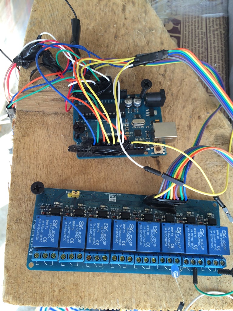
We need some cable work here so pay attention and make sure you follow example. It is for 8relay shield so some of below is not needed for you if chosen 2 relay shield. I've made it easy to understand - if not - leeme know.
// you need to share ardu 5v with relay and soilhumid
// ardu 5v to relay vcc
// ardu 5v to soilhumid vcc
// ardu gnd to soilhumid gnd
// ardu gnd (second) to relay gnd
// ardu a0 to relay a0
// ardu d6 to relay in1
// ardu d7 to relay in2
// ardu d8 to relay in3
// ardu d9 to relay in4
// ardu d10 to relay in5
// ardu d12 to relay in6
// ardu d13 to relay in7
// ardu d4 to relay in8
Easy :) ?
once you have above in place let's focus on .... electrovalve. It's easy but you need to focus x2 here.
Step 4: Cabling / Electrovalve / Gard-A-Water


Now what we're about to do is connect power adaptor to relay and from relay to electrovalve. Why ? Well if you connect power to relay Arduino will decide (based on code) when to pass current on and enable electrovalve allowing water to flow through it.
Description (see attached hand-made :) sketch) :
1. Assuming that you're using classic power adaptor that you've found in drawer - it ends with cable and some jack at the end. Cut off the jack and separate two cables. Make sure they are isolated. Name one of the cable A and the other one B.
2. Connect cable A to relay middle (you should have 3 holes there - left, mid, right) hole.
3. Take 10 meters two wire cable and cut it in half.
4. Connect one of it's cable to relay right hole.
5. Connect second cable to cable B coming out of power adaptor.
6. Ensure you isolate it properly so it does not short-circuit.
Let's summarize cause you may think it's getting hard at this point. It's not. See, there are two wires coming out of the power adaptor. One of them needs to go through the relay. It enters relay in one of the holes and exits other one. It allows arudino to control it's ON/OFF. By doing so the electrovalve opens or closes. Then two cables (the one that exit the relay and original one coming from power adaptor) goes to electrovalve. As simple as that.
Step 5: Soil Moisture Sensor. Few Important Tips.

So we have arduino now, relays, electrovalve and all necessary pipes connected. What's missing ?
Soil moisture detector. In previous steps I've described where to connect the soil moisture sensor.
Now you need to push it into your garden in a place where your sprinkler is able to reach it. Otherwise the system will water your garden for very long time - probably until the whole garden gets wet and finally water reaches the sensor. So once project is complete and running play with sensor a bit and find proper place where it gets the moisture value from the code in most effective time. I've put mine in the middle of sprinkler range. It allows it to spray over the sensor with water multiple times before it gets wet and shuts watering of the garden off.
How deep below ground surface ? I've put it in wiht 45degrees angle. Whole inside and covered it with soil so you can walk/cut the grass, etc over it.
Step 6: Coding Coding Coding


You ask for code - you have it ;)
// JS connection grid ;)
// you need to share ardu 5v with relay and soilhumid
// ardu 5v to relay vcc
// ardu 5v to soilhumid vcc
// ardu gnd to soilhumid gnd
// ardu gnd (second) to relay gnd
// ardu a0 to relay a0
// ardu d6 to relay in1
// ardu d7 to relay in2
// ardu d8 to relay in3
// ardu d9 to relay in4
// ardu d10 to relay in5
// ardu d12 to relay in6
// ardu d13 to relay in7
// ardu d4 to relay in8
#define RELAY1 6
#define RELAY2 7
#define RELAY3 8
#define RELAY4 9
#define RELAY5 10
#define RELAY6 11
#define RELAY7 12
#define RELAY8 4
void setup() {
Serial.begin(9600); //Begin serial connection
pinMode(RELAY1, OUTPUT);
pinMode(RELAY2, OUTPUT);
pinMode(RELAY3, OUTPUT);
pinMode(RELAY4, OUTPUT);
pinMode(RELAY5, OUTPUT);
pinMode(RELAY6, OUTPUT);
pinMode(RELAY7, OUTPUT);
pinMode(RELAY8, OUTPUT);
}
void loop()
{
Serial.println(analogRead(0));
//Read analog pin A0 and print it (prints newline)
if(analogRead(0)>550)
//if soil humidity above - 550 on/off (change HIGH to LOW if needed) electrovalve
{
digitalWrite(RELAY1,LOW);
delay(9000);
}
else
{
digitalWrite(RELAY1,HIGH);
delay(9000);
}
}

Step 7: That's It :))))))

Well,
I guess that's it. When you launch it you'd see amazing stuff happening. See photos, video and ask questions - I'll try to replay immediately.
The project has grown and it's 5 electrovalves (coming up to 8 in two weeks time). Board will be replaced by Arduino Yun or Udoo to control it / program via Internet. New version will have weather forecast check and nice reporting along with web page where you can launch electrovelves individually + mobile app. This is yet to come so stay tuned.
www.baronofhell.com

Participated in the
Epilog Challenge VI


