

Introduction: Watson IOT - Shipment Tracker


I am an IBMer and I enjoy making connected sensors. However, I had not taken the time to learn about what my own company had to offer in this space - until now. This is a project I developed to explore Watson IOT Services, the MQTT protocol and Node-RED. These are all technologies that provide a powerful Internet of Things platform and I was looking for a project that might put them to work.
This project attempts to solve a problem that many organizations face when they have to ship important or expensive equipment - loss or damage in transit. The idea is to develop a relatively simple and inexpensive device that could be attached to a shipment and provide alerts should the package get too hot or cold, get tipped over or dropped. The device would track location via GPS and provide updates via a WiFi connection. Some of you might question the WiFi choice but with a WiFi hotspot, one internet connection could be shared between many packages and it might make more sense than cellular.
This tracker will measure and report data on a regular interval when it detects movement. It can simply record this data in an on-line database and it could provide SMS or email alerts if the package is being mishandled.
Step 1: Build the Tracker


A word about hardware. There are many different combinations of micro-controllers, sensors and WiFi that will work with this service. I chose to build my own as I was just getting started in hardware design and this type of carrier board is a great way to get started in board design. I got a lot of help from the maker community and my local Triangle Embedded Interest Group so I believe in sharing as much as I can. Please take these guidelines as one way to get to the solution and feel free to give my suggestions.
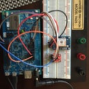
No Solder Option: I always build these devices first on a breadboard. As you can see from the Fritzing diagram above, there are a fair number of connections but building this first will give you a good sense of the circuit and get you started while you wait for the OSHPark board. Please note that the WiFi and GPS modules can draw a fair bit of current so, I added decoupling caps and you may want to place them close to theses modules. Also, this circuit will stop working when the LiPo battery drops to 3.75V where it still has about 30% charge. Because of this, I added a switching buck-boost power supply to my board below so I could get more from each recharge.
Ready for Travel Option: Given that this device was to travel with a package and needed to work while being shaken and potentially dropped, I decided to build a carrier board to hold the various components and to handle power management. You can order this board directly from OSHPark here. You will also need the parts which are outlined in the attached BOM. If you would like to improve this board (Please do, and then share your improvements!) you can start with the EAGLE design files which I have shared on Github here.
I started this project using the Atmel 328p but soon came to a realization, with WiFi, I needed more working memory and would need a more powerful chip. After some trial and error, I decided to use the wonderful Teensy 3.2 from PJRC. This is an Arduino compatible ARM processor with much more memory and speed. The basic build contains the following components:
- Teensy 3.2 – $17 from OSHPark – Microcontroller
- MMA8452 -$9.95 from Sparkfun – to sense movement
- Ultimate GPS – $39.95 from Adafruit - for location
- CC3000 Breakout – $25.50 Allied Electronics – TI’s powerful WiFi module on a carrier board
- Custom Carrier Board – $12 from OSH Park min qty 3 – Power Supply and Connections
You can hand solder the components on the board but the TI Power Chip is a little harder with the PowerPad and the QFN packaging. You may want to review this video for the proper technique.
Finally, I needed to build a quick analog temperature sensor. I did not have time to order an analog temperature sensor one so I built something quick that worked out very well. I built a voltage divider with a 10k NTC 3950 thermister and a 10k resistor. You can use your own sensor or build one like mine by following this tutorial from Adafruit.
Step 2: Sign Up (Free!) for Bluemix and Deploy the Watson Internet of Things Service


Signing up for Bluemix is a fairly painless process. You get a 30 day trial for free so you can try this Instructable without having to whip out the credit card. Go to Bluemix.net and sign up then, select the "Take Advantage of IOT" option which will install the "Internet of Things Platform Starter" which is a boilerplate that contains three main components: a Node.JS environment, a Cloudant No-SQL database and the Watson IOT Platform.
Give your service and name and create it using the button provided. You can also see what the charges for this service will be once your trial is over. Most services on Bluemix include a "free tier" and generally you can stay under these limits indefinitely as you develop and refine your project. That said, this service will automatically scale as you add tens, hundreds or thousands of sensors.
Now that we have the service up and running, and our device ready to go, we can get connected.
Step 3: Get Your IOT Device Connected to the IOT Platform


Now that you have your tracker and the Bluemix Internet of Things Platform Starter, it is time to get connected. Here is a high-level picture of what we need to do here. Here is an overview of the process: First, you need to register your device with your IOT service so when you start sending data, Watson will be expecting you. Then, you add the credentials from registration (a user ID, a device ID and an authorization token) to the provided sketch.
To get started, we need to register our device with the IOT Platform. As a prerequisite, you will need the MAC address of your Wi-Fi breakout. This can be determined using the command getMacAddress(uint8_t address[6]) in a sample sketch or by looking at your router's wireless information tab once you connect. With the MAC address in hand, you are ready to register your device. To do this, launch the IOT Platform Dashboard and select the "Devices" page from the icons on the left. Then, select "Add Device" and complete the registration steps. You will also generate an access token in this process. You need to write this number down in this process as it will not be displayed again.
At the end of this process, you will have the following information:
- Organization ID
- Device Type
- Device ID
- Authentication Method
- Authentication Token
- Your WiFi SSID
- Your WiFi Password
- Your WiFi Authentication method
- Your CC3000's MAC address (same as the Device ID)
Edit the Sketch I have shared here and replace the place holders with these values. I use a Mac and love using Apple's XCode as my IDE. I do this using an excellent program called embedXCode which I cannot recommend highly enough for Mac users ready to trade up from the Arduino IDE. Because of this, there is some extra code at the top of the sketch which you can ignore. This sketch will verify and upload in the standard Arduino IDE.
Run this sketch and you will have succeeded when you see your data elements displayed in the "connections" section. Then, we will be ready to do some cool stuff.
Step 4: Format and Send Data
Now that we are connected, what will we send to the Watson IOT service? The answer is a structured form of communications called JavaScript Object Notation. This is simply a way of structuring data so the Watson IOT service can make sense of it. The basic format is Key:Value pairs enclosed in brackets. When typed, our JSON payload will look like this:
{
"d": {
"TempC": 28,
"Orient": 3,
"lat": 39.03, "lng": -77.14,
"aX": -3, "aY": 0.1, "aZ": 0,
"Tap": 1
}
}
I have added line breaks and tabs to make the structure more apparent but they don't matter to the service. Think of this as a set of information called "d" which contains values for temperature, orientation, location, acceleration and drop detection. Each of these "key : value" pairs will be parsed by the Watson IOT service and passed on to Node-Red for further processing. As each implementation of the IOT device will vary, I don't want to go into too much detail but, here is a high-level view of how I build this JSON payload on the IOT device:
- Temperature. I chose to build a simple Thermistor temperature sensor. This is an accurate and inexpensive analog sensor which the microcontroller can measure using an Analog input pin and the AnalogRead command. Adafruit has written a great tutorial on how these readings are converted to temperature here.
- Acceleration. We are using the Freescale MMA8452 Accelerometer but any I2c digital accelerometer will do. This sensor, which costs less than $2, is an amazing device. Using an MEMS device (think of a tiny mass supported by three sets of orthogonal springs), you can determine the instantaneous acceleration. The sensor can then do some calculations and signal "interrupts" if the magnitude of the acceleration vector exceeds a specific value (tap) or if the sensor is in a different orientation with respect to ground (orient). The implementation of these capabilities are done in a library which is either provided by the manufacturer, the reseller (as in this case Sparkfun) or which you need to write yourself. Once you have a library included in your sketch, you can call for these values using a statement like this to read the six raw data (2 for each axis) registers into data array: readRegisters(MMA8452_ADDRESS, 0x01, 6, &rawData[0]);
- The Orientation and Tap values are read only after their respective interrupt flags indicate there is "new news" but the process is similar to get the values. These interrupt "flags" are very useful as you can save significant power by putting your device to sleep and using a change in these values to wake the device and report the new readings.
Since this device uses standard i2c communications, you could add other sensors to measure humidity, UV light exposure, radiation etc. The only limitation is that the total length of the JSON package needs to be less than 100 characters. This is a limitation of the WiFi module and could be expanded if you used a newer board. Limitations such as this, as well as significant limitations on power and processing are the types of boundary conditions that make embedded systems different from desktop or web development. While they can be challenging, I enjoy working to find the best balance.
Step 5: Use Node-Red to Put Your Data to Work


Node-Red was a open source project created by IBM back in 2013. IBM has continued to support the project but it also has a very active user community and a significant list of supported "nodes" for popular open source and commercial products. I like the visual metaphor it uses with specific "nodes" which are connected into "flows". In this use case, we will use Node-Red to take our JSON payload from the last step and make some decisions about what this data is saying about our package. We will also use Node-Red to send each datapoint to a Cloudant database. If you have not used Node-Red yet, you may want to watch this short YouTube video to get a sense of what it can do.
You can import my Node-Red process very simply. By following these steps:
- Download the Node-Red.JSON file from my Github Repository.
- Copy the text in this file to your clipboard
- Click on the little menu button in the upport right hand corner of Node-Red and select Input - Clipboard
- Past the contents into the window and push the "Deploy" button.
I will also describe the steps I used to create the Node-Red flows here:
To connect the data from the Watson IOT service to Node-Red, you need to drag the "IBM IOT" node from the input pallet on the left. Double-click on the node and enter the device ID from your Watson IOT dashboard for the device you created and you are connected. You can use a debug node to see the raw JSON data which I have highlighted in blue in the image above.
Now that we have connected our data feed from the device to Node-Red, we will create a flow with three main branches:
- First, we will capture each data point sent by our sensor in a Cloudant database. This is very straightforward as you simply drag a Cloudant database from the storage palette and connect it to the "IBM IOT" node. This will ensure you have a record of each data point and Cloudant has powerful features to do geo-spatial and temporal analysis once you can accumulate data from multiple shipments. This information can help you see where shipments are damaged and focus remediation efforts where they will have the biggest impact. An alternative to Cloudant could be a block chain where you could use this data to enforce smart contracts with your shipper. More on this later.
- We want to set some alerts for temperature and dropping. To do this easily, I split the JSON package and insert a switch on the TempC and Tap fields. These switches allow me to define limits on temperature or determine if a tap has been detected and then generate a message. In this example, I am using Twilio to send an SMS if the package is dropped or an eMail if the temperature goes out of bounds.
- Finally, I want to show how we can do more complex analysis on the data using functions. This is a very powerful feature as the functions allow you use to Java-Script to do work that would be much harder in the C programming language that the microcontroller uses. I love C but it is not a great language for parsing strings and complex math requires loading additional libraries which reduce memory and can impact battery life. Take a look at the "Tilt" function in my flow and you will see how we convert the accelerometer readings into tilt angles. This math is much easier to do in Java Script.
One last comment on the power of this approach, by simply sending raw data from the IOT device and using functions in Node-Red to analyze the data and determine what is acceptable, we make it much easier to make global changes to our tracker over time. Imagine if we get to the point where there are hundreds of these devices. Changing sensitivities or determining what is acceptable temperature ranges can be done once in Node-Red without having to update the devices in the field. This approach also helps keep the connected devices simple and inexpensive.
I hope this tutorial has been helpful, please send me comments on how to improve it.

Participated in the
IoT Builders Contest


