

Introduction: Wii Remote IR Camera Hack With Arduino Interface


We'll physically extract the IR camera from the Wii remote and interface it with an arduino controlling a servo.
The Wii IR camera is a beautiful thing. It has an integrated processor which outputs the X and Y positions and size of the 4 brightest IR points that is sees. This can be very useful for tracking in robotics or human interfaces. Enjoy!
Step 1: Extract the Wii IR Camera


You'll need a Wii remote or "Wiimote" to start with. Normally they are about $40, in the end that is not too bad for a pretty awesome sensor. Otherwise you can check out ebay or elsewhere for used or broken Wii remotes.
You'll need to rip apart the case. It has some crazy three pronged screws. I didn't want to completely trash the case so I made a small tool to take it apart.
Now you need to desolder the 8 pins and the 2 struts holding the camera on the board. I used some desoldering braid. It wicks the solder away and makes it easy to get the camera out. Be careful, don't break the camera!
How to use desoldering braid: http://www.youtube.com/watch?v=AcbezX8TrOU
You might want to keep the rest of the parts. You might be able to scrap other parts. Also, If you decide later to use the Wiimote again, you could always put the camera back in.
Step 2: Interface Circuitry

We'll need a small circuit to interface the IR camera to the arduino. I got all my information from other sources. Here is an exhaustive list:
This fellow (kako) seems to be the first. Here are his pages translated. (Please note that the various translation services online all give slightly different results. It is useful to try several of them.)
http://translate.google.com/translate?u=http%3A%2F%2Fwww.kako.com%2Fneta%2F2008-009%2F2008-009.html&hl=en&ie=UTF-8&sl=ja&tl=en
http://babelfish.yahoo.com/translate_url?doit=done&tt=url&intl=1&fr=bf-home&trurl=http%3A%2F%2Fwww.kako.com%2Fneta%2F2007-001%2F2007-001.html&lp=ja_en&btnTrUrl=Translate
Johnny Lee did his part as well and he has some good information:
http://procrastineering.blogspot.com/2008/09/working-with-pixart-camera-directly.html
But the most useful information came from Stephen Hobley. He is going to supply us with the arduino Wii camera library which we will use while programming.
http://www.stephenhobley.com/blog/2009/02/22/pixart-sensor-and-arduino/
http://www.stephenhobley.com/blog/2009/02/24/all-in-one/
http://www.stephenhobley.com/blog/2009/03/01/pixartwiimote-sensor-library-for-arduino/
Ok, to the circuit. We need the clock circuitry and the i2c interface. Do you want to undertand i2c? Don't ask me: http://en.wikipedia.org/wiki/I%C2%B2C
Here is a direct link to the schematic shown below (so you can actually read it.) http://stephenhobley.com/blog/wp-content/uploads/2009/02/wiicam_schem.gif
The clock is pretty simple. You need two capacitors, a 25 MHz crystal, a 1 Meg Ohm resistor and a 74AC04 inverter logic gate. These are all pretty standard parts, you can get them all from Digikey.com or other online electronics sites.
We'll handle the i2c circuit in the next step.
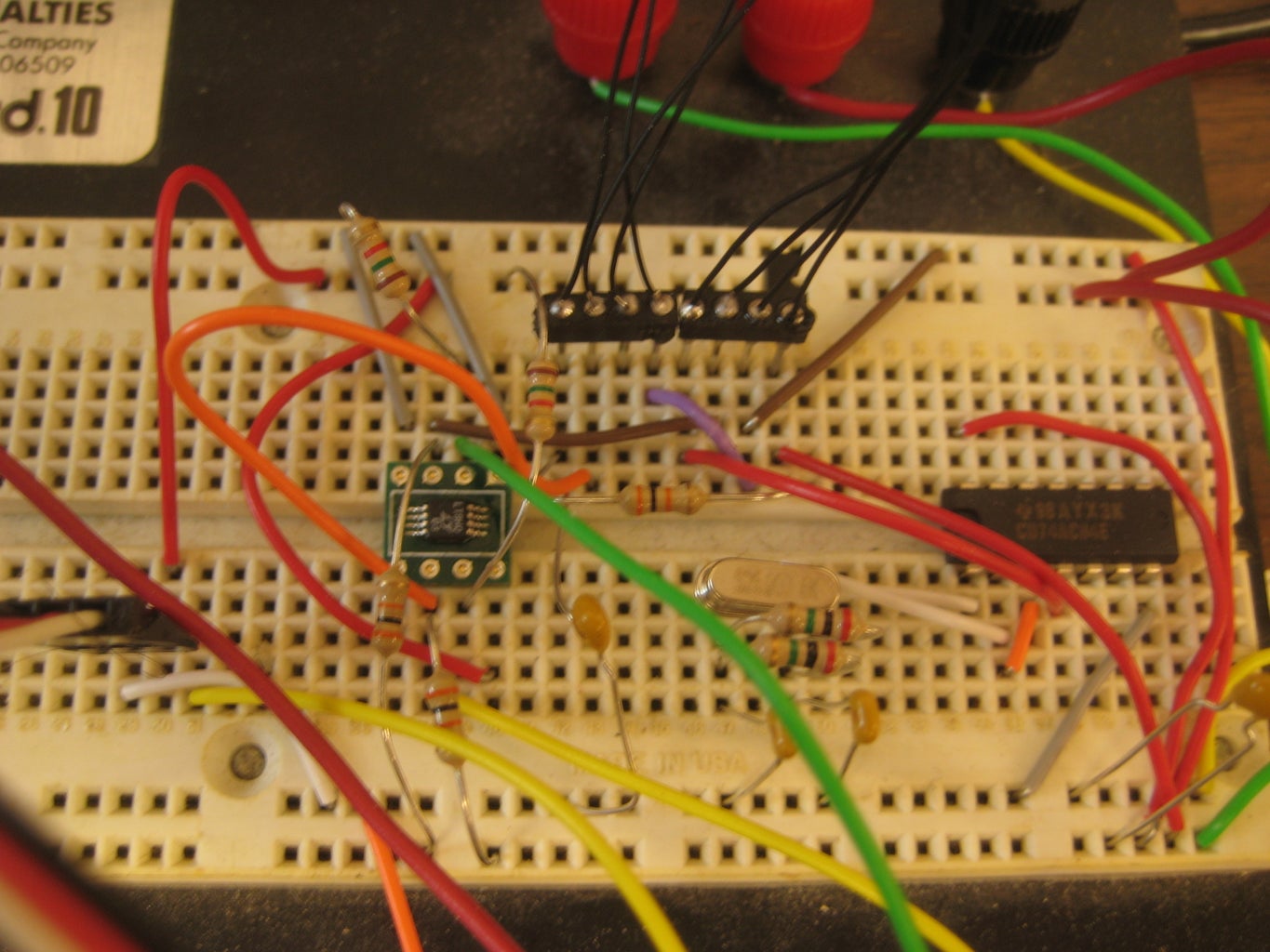
Step 3: I2c Circuit


This part is a little trickier. The i2c chip is a tiny surface mount chip, so you'll need to solder that. First you need the surface mount to DIP board. This will allow us to work with the tiny chip in a prototyping circuit. This chip is the communication device between the 5 volt arduino and the 3.3 volt Wii camera.
The chip:
http://search.digikey.com/scripts/DkSearch/dksus.dll?Detail&name=LTC4301LCMS8%23PBF-ND
The surface mount to DIP adapter:
http://cimarrontechnology.com/msop-8sot-23-8to8-pindipadapterpn030502.aspx
Here is a great video, which explains, far better than I can, how to solder those darn surface mount chips.
http://www.youtube.com/watch?v=3NN7UGWYmBY
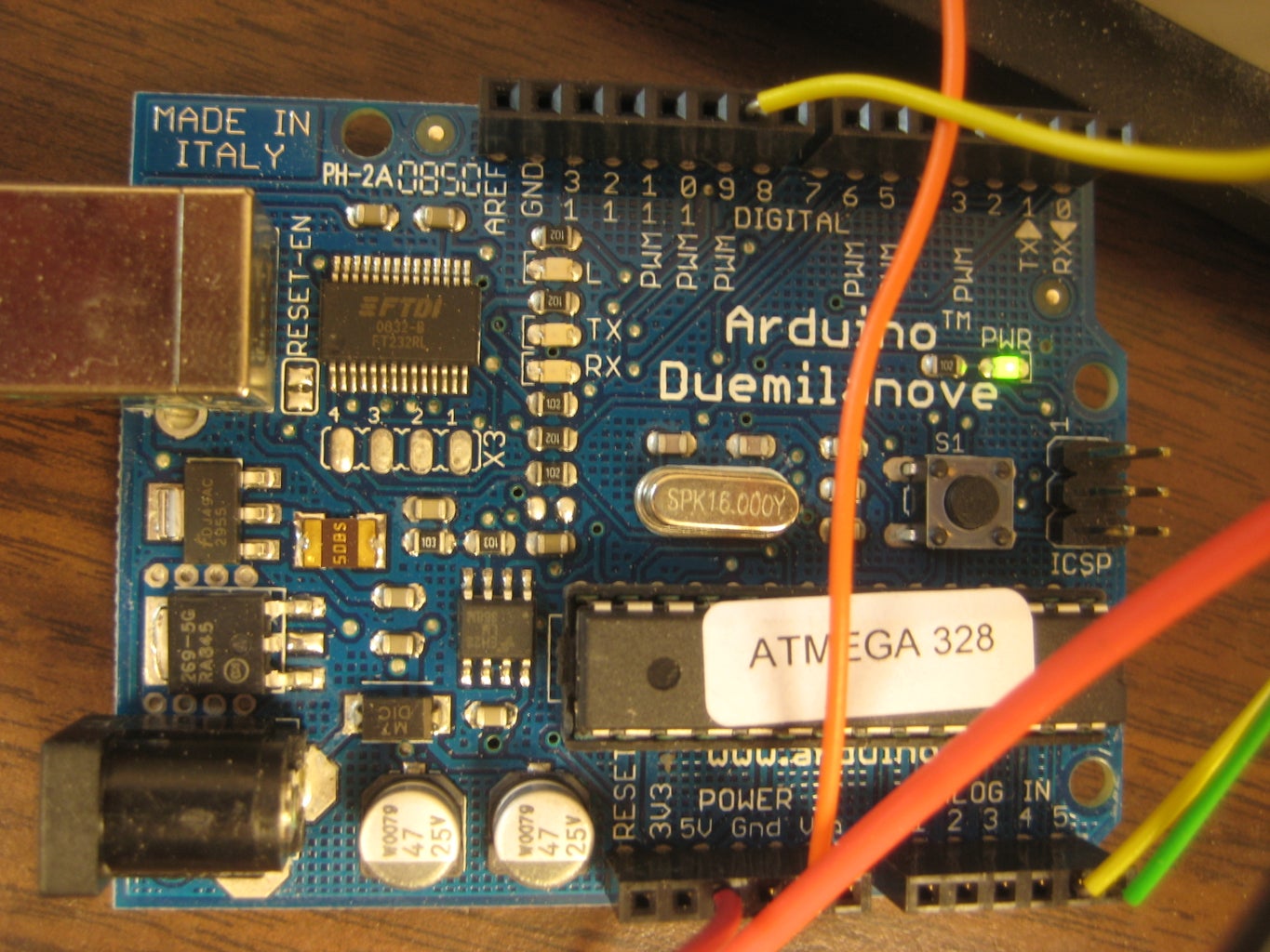
Step 4: Attach It All to the Arduino
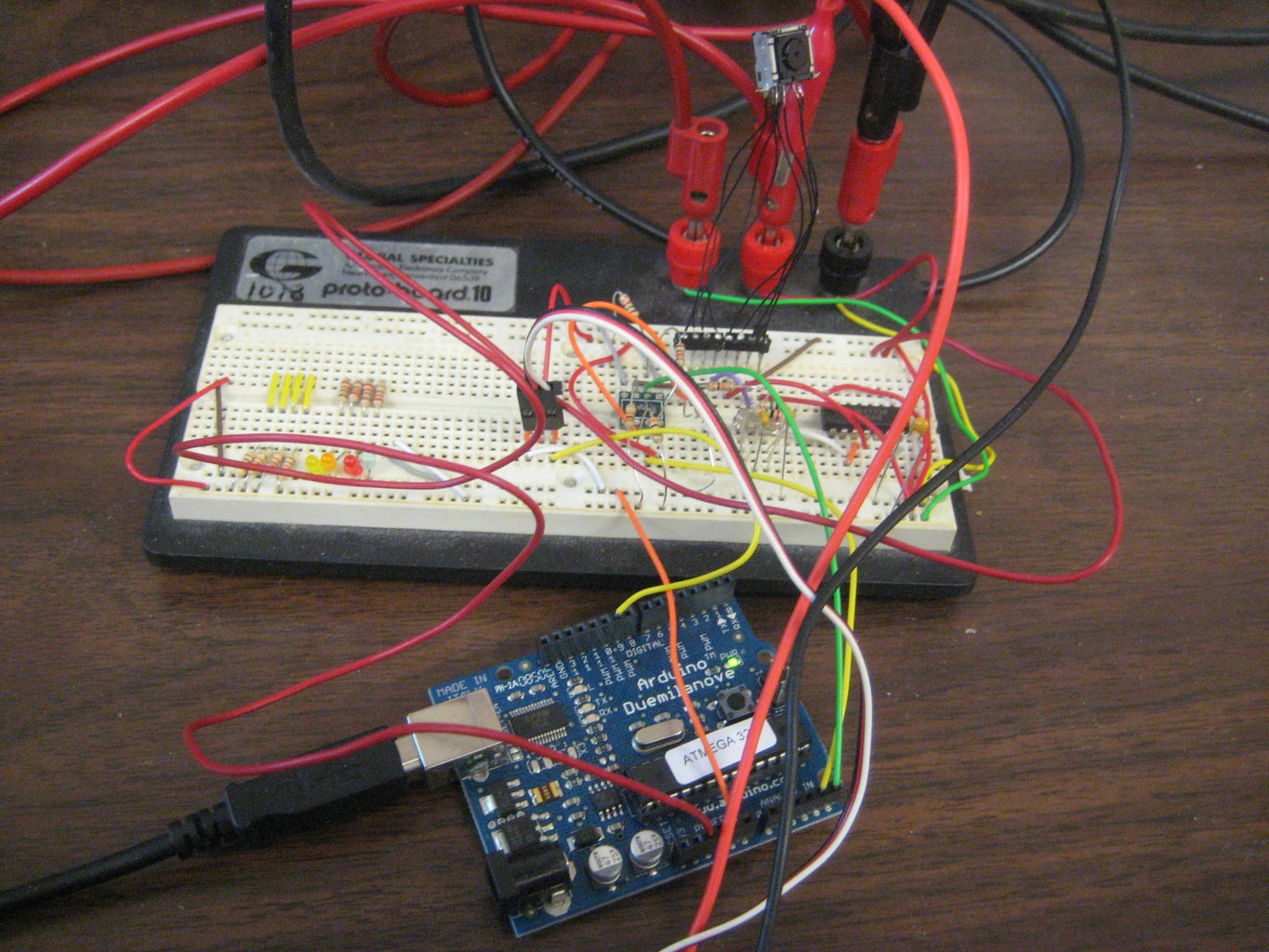
All of the IR camera to i2c and clock connections are shown in the Stephen Hobley schematic (check out the previous steps.) http://stephenhobley.com/blog/wp-content/uploads/2009/02/wiicam_schem.gif
You'll need to connect the arduino to the i2c chip, (also shown in the schematics) and connect the servo to the arduino (I have mine on pin 9, just like in the arduino servo example.)
The arduino chip requires +5 volts and the camera requires +3.3 volts. I had a multiple output power supply, so I gave each part of the circuit what it needed. If you only have a +5v power supply you could add a 3.3 volt voltage regulator to drive the camera.
Step 5: Program the Arduino


This is pretty easy and the fellas who I've linked to worked out most of the details. Good thing, we can get straight to playing around with it.
If you need information about arduino's, just google it. I found all of my info there easily. Here is the main arduino page: http://www.arduino.cc/
First thing, get the servo working. Run the servo example code in the arduino programmer to get your feet wet.
Second, download Stephen Hobley's Wii camera library and example code. Here: http://www.stephenhobley.com/arduino/PVision.zip
Connect the arduino to the same pins that he used. Make sure your i2c circuit and clock are all connected and the power is on and then run the code. You may need to insure that the Pvision.h file is in your arduino library so that is it properly reference when compiling.
Once running, in the serial I/O stream in the arduino programmer you should see data coming in as long as the camera sees some IR light.
I first used a match to check the camera. It worked fine. Later I used an IR led since I needed something a little more steady (and less burny.) You can use a digital camera to see if your IR LED's are working. The camera image sensor picks up the IR light that your eyes cannot see. This is a reassuring way to truly know if the LED's are working.
Step 6: Using the Camera to Control Something.


I have attached the arduino code files.
The system responds very quickly, even to fast, small movements. Now, we can use the Wii camera directly in all our projects. Look for cheap busted Wii remotes on ebay to salvage.
If you are getting too much noise in the system (i.e. the camera is seeing too many extraneous light sources) you can use the IR filter from the Wii remote. This will filter the lights which are disrupting the camera.


