

Introduction: Wireless Garden System


This project is based on Arduino, and uses "modules" to help you water your plants, and get log on temp and soil and rain.
The system is wireless thru 2,4 GHz and uses NRF24L01 modules to send and receive data.
Let me explain a little on how it works, PS! Excuse me if the English is not 100 % correct, I'm from Sweden.
I use this system to control my plants, sins I have differents plants i needed to log them different.
So I build a zone based log system.
The Soil sensors that reads the soil moisture and temp, (runs on battery) checks every hour and pass the data to the base machine that have an wifi connection. The data is uploaded to a server in my house and logs on to a webpage.
If the soil needs water, it will activate correct pump depending on what soils sensor has checked. But if it raining it will not water. And if it really hot it will water some extra.
Let's say you have one potato land, one for tobacco and one for tomato, then you can have 3 zones with 3 different sensors, and 3 pumps.
There is also pir sensors that checks for movements, and if them is activated on the webpage a loud siren will start to scare the animal or the person that is walking close to my plants.
Hope you understand a little. Now lets start making som sensors.
My GitHub page where you download everything: https://github.com/shootinggame82/Wirelsess-Garden-System
Step 1: Soil Sensors


Each sensor has a unique number that is added to the webpage. So when the soil sensor is transmitting the data from that soil sensor will be added to the correct zone. If the sensor is not registrated, well no data will be submitted.
For this build you need:
- 1x Atmega328P-PU chip
- 1x nRF24L01 module
- 1x 100 uf Capacitor
- 1x NPN BC547 Transistor
- 2x 22 pF Capacitors
- 1x 16.000 MHz Crystal
- 1x Soil Mouisture sensor
- 1x DS18B20 Temp sensor
- 1x RGB Led (Common Anode is used by me)
- 3x 270 ohm resistors
- 1x 4,7 K ohm resistor
- Battery (I use 3.7v Li-Po battery)
- And if li-po is used, a charger module for battery.
To keep the sensors running a long time, don't use any pre made Arduino board, they will empty the battery quick. Instead use the Atmega328P chip.
Connect everything as it shows in my electric sheet. (See image or PDF file) Recommend is to also add an power switch, so you can cut the power when charging.
When uploading the code, don't forget to define sensor to give them a unique ID number, the code is available on my GitHub page.
To keep the soil sensors alive for a long time, I use an NPN transistor to power them up, only when the reading begin. So they are not activated all the time, Each sensor has an ID number from 45XX to 5000 (this can be changed) so each sensor must have unique numbers, all you need to do is to define in the code.
The sensors will go to sleep to save battery.
Attachments

Step 2: Animal Sensor


The Animal Sensor is an simple pir sensor. It sense the heat from animals or humans. If the sensor is sensing movement. They will send out to the base station.
But there will not go on any alarm, to do so, on the page you have to activate it, or if you have setup an timer it will activate automatic that time.
If the base get movement signal from the Animal sensor, it will pass it on to the Siren sensor and it will (I hope) scare the animal away. My siren is at 119 db.
The pir sensor runs on battery and i have placed it in an old pir sensor case from an old alarm. The cable that is coming out from the animal sensor is just to charge the battery.
For this sensor you need:
- ATMEGA328P-PU chip
- 1 x 16 000 MHz Crystal
- 2 x 22 pF capacitor
- 1 x Pir sensor module
- 1 x 100 uF capacitor
- 1 x NRF24L01 module
- 1 x Led (I don't use any RGB led here)
- 1 x 220 ohm resistor
- If you will run on a battery you need that (I use Li-Po)
- A battery charger module if you have a recharge battery.
- Some kind of power switch.
Connect everything as you see en the electric sheet. Check so you can power your pir sensor from you battery (Some needs 5v to run).
Get the code from my GitHub and define witch sensor you are going to use (Ex: SENS1, SENS2 etc) so they get unique numbers.
The ATMEGA chip will only wake up when movement is registrated. Sins the pir sensor module has built in timer for delay there is nothing for that in the code, so adjust the pot on the pir sensor for the delay it will be awake.
Thats it for the animal sensor, we are moving on.
Attachments
Step 3: Water Pump Controller


The water pump controller is to start a pump or water valve to water your fields.
For this system you don't need a battery sins you need power to run your pump.
I use a AC 230 to DC 5 v module to run an Arduino Nano. Also i have to types of pump,
One that uses an Water valve that runs on 12 v so for that I have a AC 230 to DC 12v module to the relay board.
The other is 230 AC in to the relay so i can power an 230 V AC Pump.
The system is quite simple, each pump controller has unique id numbers, so let's say the potato field is dry and the sensor is set to auto water, then my pump that is for the potato field is added to that sensor, so the soil sensor is telling the base system that the watering should start, so the base system send out an signal to that pump to activate.
You can set how long it should run on the webpage (for example 5 minutes) sins the sensors only check every hour. Also when the pump stop it will store the time in the system so the auto system not will start the pump to soon. (Also possible to setup on the webpage).
You can also thru the webpage disable watering during the night/day by setting special times. And also setup timers for each pump to start watering. And if it rains they will not watering.
Hope you understand :)
For this project you need:
- 1 x Arduino Nano
- 1 x NRF24L01 module
- 1 x 100 uF capacitor
- 1 RGB Led (common anode is used by me)
- 3 x 270 ohm resistors
- 1 x relay board
Connect everything as the electric sheet (see pdf file or image)
Download the code from GitHub and don't forget to define the sensor number.
And now you have an pump controller, the system can handle more than just one.
Attachments
Step 4: Rain Sensor


The rain sensor is used to detect rain. You don't need more than one. But it's possible to add more.
This rain sensor is battery powered and checks every 30 minutes for rain.
They also have unique number to identify them self.
The rain sensor is using analogue and digital pins. The digital pin is to check if it rains, (The digital only display yes or no) and you have to set the pot on the rain sensor module on when it's ok to warn about "raining" (the level of water on the sensor that indicates raining.)
The analogue pin is used to inform in percent how wet it is on the sensor.
If the digital pin detects that it's rain, the sensor will send it to the base system. And the base system will not water plants as long it's "raining". The sensor also send how wet it is and battery status.
We only power the rain sensor when it's time to read thru the transistor that enables thru an digital pin.
For this sensor you need:
- ATMEGA328P-PU chip
- 1x 16 000 MHz Crystal
- 2x 22 pF Capacitor
- 1x Rain sensor module
- 1x 100 uF capacitor
- 1x NRF24L01 module
- 1x RGB Led (I used common anode, it's VCC instead of GND)
- 3x 270 Ohm resistors
- 1x NPN BC547 transistor
- 1x Battery (I use Li-Po)
- 1x Li-Po Charger module (if used Li-Po battery)
Connect everything as you see on the electric sheet (in pdf or in the image
Then upload the code to the ATMEGA chip as you can find in my GitHub page under Rain sensor
Don't forget to define the sensor to get the right id number.
And now you will have an rain sensor that runs every 30 minutes.
You can change the time on this if you wan't it less or more.
In function counterHandler() you can setup the wakeup time for the chip.
You calculate like this: The chips wake up every 8 seconds and every time it will increase a value.
So for 30 minutes you will get 225 times before it should do actions. So there are 1800 seconds on an half hour. So divide it by 8 (1800 / 8) you will get 225. That means that it will not check the sensor until it runs 225 times and that will be about 30 minutes. You do the same on soil sensor also.
Attachments
Step 5: Animal Siren


The animal siren is simple when the animal sensor detects motion the siren will be activated.
I use an real siren so i even can scare people with it. But you can also use sirens that only animals hear.
I use an Arduino nano in this project and power it with 12v. The siren is also 12 v so instead of an relay i will use an 2N2222A transistor to enable the siren. If you use an relay when you have the same ground you can damage your Arduino. So thats why i use an transistor instead to enable the siren.
But if your siren and Arduino don't use the same ground, you can use an relay instead. Skip the transistor and the 2.2K resistor, and use an relay board instead. And also change in the Arduino code when activated change from HIGH to LOW and when inactivated change from LOW to HIGH och digital read for the pin 10, sins the relay uses LOW to activate and the transistor uses HIGH so you need to switch this.
For this build you need:
- 1x Arduino nano
- 1x 2.2K Resistor (Skip if using relay board)
- 1x 2N2222 Transistor
- 1x Siren
- 3x 270 Ohm Resistor
- 1x RGB Led (I use common anode, VCC instead of GND)
- 1X NRF24L01 module
- 1x 100 uF capacitor
Connect everything as you see on the electric sheet in PDF or in the image.
Upload the code to the Arduino that you find on my GitHub page under Animal Siren
Don't forget to define the sensor for correct ID number.
And now you have an working siren.
Attachments
Step 6: Main System


The main system is the most important of all modules. Without it you can't use this system.
The main system is connected to internet with the ESP-01 module and we are using Arduino Megas Serial1 pins to connect it. The RX on Mega to TX on ESP but we need to go thru two resistors to get the volt down to 3.3. And the TX on Mega to RX on ESP.
Setup the ESP Module
To use the ESP you first need to set the baud rate on it to 9600, it's what i have used in this project and i have found that the ESP works best so. Out of the box it set to 115200 baud rate, you can try it but mine was not so stable. To do it you need an Arduino (Mega works good) and you need to connect the TX of ESP (thru the resistors as you see on the sheet) to the Serial TX (not Serial1 if using Mega) and RX on ESP to Arduino Serial RX.
Upload blink sketch (or any sketch that don't use serial) and open serial monitor and set baud rate to 115200 and NR & CR on lines
In command line write AT and press enter. You should get a respond that says OK, so now we know that the ESP is working. (If not there is connection problem or bad ESP-01 module)
Now in the command line write AT+UART_DEF=9600,8,1,0,0 and press enter.
It will respond with an OK and this means we have set the baud rate to 9600. Restart the ESP with the following command: AT+RST and press enter. Change baud rate in serial monitor to 9600 and enter AT and press enter. If you get OK back, the ESP is setup for 9600 and you can use it for the project.
The SD Card Module
I want it to be easy to change the WIFI settings for the system, incase a new password is changed or wifi name. So that is why we need the SD Card module. Inside the SD Card create a text file with the name config.txt and we are using JSON to read, so we need an JSON format. So the text file should have the following text:
{
"ssid": "YOURWIFISSID",
"losen": "YOURWIFIPASSWORD"
}
Change the text with the BIG letters to correct for your wifi network.
Sins we are using NRF24L01 that uses SPI and the SD Card Reader also uses SPI we need to use the SDFat library so we can use SoftwareSPI (we can add the SD card reader on any pins)
DHT Sensor
This system is placed outside and has an DHT sensor so we can check the humidity and temp of the air. It's used for extra watering on hot days.
For this build you need:
- 1x Arduino Mega
- 1x NRF24L01 Module
- 1x ESP-01 Module
- 1x SPI Micro SD Card Module
- 1x DHT-22 Sensor
- 1x RGB Led (I used common anode, VCC instead of GND)
- 3x 270 Ohm resistors
- 1x 22 K Ohm resistor
- 2x 10 K Ohm resistor
Please note that if you don't get you ESP-01 module stable try to power it from an external 3.3v power source.
Connect everything as you see in the electric sheet in the PDF file or in the image.
Upload the code to your Arduino Mega, and don't forget to check the entire code for comments, because you need to set the host to the server on multiple places (it's not the best solution i know).
Now your Base system is ready to use. You don't need to change variables in the code for soil moisture sins you can do it strait from the webpage.
Attachments
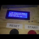
Step 7: The Web System


To use the system you also need an web server. I use an raspberry pi with Apache, PHP, Mysql, Gettext.
The web system is multi language so you can easy make it in your language. It comes with Swedish and English (the English can have incorrect english, my translation is not 100 %.) So you need to have Gettext installed for you server, and also the locales.
I show you some screenshots above from the system.
It's comes with an simple login system and the main login is: admin as user and water as password.
To use it you have to setup three cron jobs (you find them under cronjob folder)
The timer.php file you need to run every seconds. This holds all the automation for the hole system.
The file name temperatur.php is used to tell the system to read the air temperature and log it. So you need to setup an cron job on how often you are going to run it. I have it every 5 minutes.
Then the file called dagstatistik.php should only run one time before midnight (like 23:30, 11:30 PM). It takes values reported from sensors during the day and save it for week and month statics.
Please note that this system stores temperature in celsius, but you can change to Fahrenheit.
In the db.php file you setup the mysql database connection for the system.
First, add the sensors to the system. And then make zones, and add sensors to the zones.
If you have question or find bugs in the system, please report them on the GitHub page.
You can use the web system and you are not allowed to sell it.
If you have problems with the locales for gettext, please remember that if you use raspberry as server they are often named like en_US.UTF-8 so you need to make those changes in the i18n_setup.php file and under locale folder. Otherwise you will be stuck with Swedish language.
You download it on the GitHub page.


