

Introduction: Wireless RFID Door Lock Using Nodemcu

--- Main Function ---
This project was build as part of a Network Communications class at Universidade do Algarve in collaboration with my colleague Luís Santos. Its main purpose is to control the access of an electric lock through wireless with the use of RFID tag cards or key rings.
Although this project was designed to work with a door lock, it can be easily modified to support any kind of solenoid switch (this will be referred further during this tutorial).
--- Present Version ---
This first version will be done with the support of a server and a simple txt file. In future work, there'll be added different variants that will suit different needs and present a more secure alternative.
--- Future Work ---
When I find some free time I'll try to update the following features:
- Special Administrator card to add other users
- Access the file through the router's USB mounted storage
- Encrypt the file with a simple binary key
- Connect a real solenoid lock to the relay and update the Instructables with a working video
- Connect to a DBMS for ease control and maintenance of multiple locks and users
- Add a local MicroSD file to backup the information in case of Wireless unavailability
- Connect through a GSM GPRS Communications Module
- Make it working with a solar panel to be absolutely wireless
Step 1: Components Required

The components needed for this project are:
- NodeMCU ESP8266 WIFI Development Board
- DC 5V 1 Channel Relay Module
- RC522 Chip IC Card Induction Module RFID Reader
- RFID Tag Cards or Key Rings
- Solenoid Switch Door Lock
- One Diode from 1N4001-1N4007
- Cables
- Breadboard
Extra:
- RGB 3 Color Led Module 5050 or:
- A Red LED and a Green LED accompanied by 220ohms resistor
- 0.96 Inch 4Pin Blue Yellow IIC I2C OLED Display Module
Curiosity: NFC is a subset within the RFID family and operates at the same frequency (13.56 MHz).RC522
Step 2: Connecting the Nodemcu to a Wi-fi Network

There are already good tutorials that can help you connect the NodeMCU to any 802.11 wireless networks. The one we followed was:
Installing ESP8266 Into Arduino IDE Tutorial by Mybotic
Note: Beware that the pin layout on the NodeMCU is different from the Arduino, and so, if you use p.e.: #define Led 5 is actually connected to D1 on the board, as it can be seen in the above figure.
One solution is the inclusion of a library that already does this association. We simply followed the image to guide us. Later in this tutorial there'll be an image with all the connections done.
Step 3: Connect the RFID Reader

Go to Manage Libraries... inside the Include Library under Sketch in the Menu Bar.
On the text box with the "Filter your search..." insert MFRC522 and choose to install the one that is by GithubCommunity, with the designation Arduino RFID Library for MFRC522 (SPI).
--- Reading RFID Cards ---
If you wish to test the RFID reader, go to Examples under File in the Menu Bar and search for MFRC522 and choose the ReadNUID to tried it.
Step 4: Setting Up the Base Configuration

First, we'll assembly the base configuration following the circuit's diagram shown above (if you click on the image there's additional information about the pin layout).
Then, connect the NodeMCU and open the Arduino IDE and copy the code bellow.
Don't forget to replace the ssid and password for the ones of your network, and your server host address on the code.
Attachments

Step 5: Creating the Txt File With the Cards' Ids

If you already tested the previous step, it probably didn't happening anything when you tried approaching the cards to the RFID reader. That's OK! You still need to add the cards you desire to your server (there'll be other alternatives in the unforeseen future).
First, you'll need to have your server up and running. Create a .txt file anywhere you desire and open the Serial Console on your Arduino IDE. Run the code and copy the RFID MAC address that is presented, paste it to the .txt file and press Enter, so that there's always an empty line at the end. Save the .txt file and try it again.
Now it should work, you don't have to reset the NodeMCU or restart the server.
The ON LED color that comes with the relay is usually red and so, if the lock is open, it should shine red. On a further customization we'll try to change this LED to offer a permanent red status and a green status without the need to use additional ports on the NodeMCU board.
Note: don't forget to change the folder's location on the url inside the code.
Step 6: Connecting the Relay to a Solenoid Switch

Attention, this step is important.
Solenoid switches are but coils that with current create a magnetic field that pulls or push a piston. They may come like solenoid valves, door locks, switches, etc...
What you need to do carefully are two steps:
- Connect your energy source and solenoid switch to the relay in the correct way, as shown above;
- Connect a diode between the two pins of your solenoid switch for circuit protection.
Step 7: Extra: Adding RGB Leds
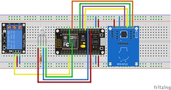
Just follow the above circuit's diagram and don't forget to add a 220 ohms resistor between the anode and ground.
If the light is too dim or too bright, you can change the value of the resistor (just don't jump from a 220 ohms resistor to a 1M ohm resistor and pretend to be perplex with the results).
Attachments
Step 8: Extra: Adding a OLED Screen
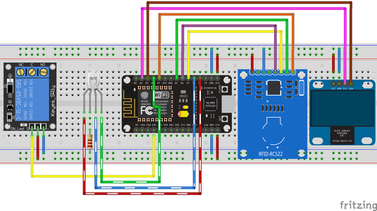
As before, you just have to follow the circuit's new diagram above and the code bellow.
The future mais purpose of the OLED screen is not to simply replicate the RGB function, but to allow for additional informations to the user if required.
Attachments
Step 9: Final Configuration


Above it's possible to see this project working though a video and a couple of images, running with the complete code, including the extras.

Participated in the
Invention Challenge 2017


