

Introduction: Wireless Firework Igniter


Firework is great for parties, but lighting them can be dangerous. That's why I made a wireless igniter, with an infrared remote control and an arduino. The project is powered by a NiCd battery (from a cordless drill), and is entirely stored in a small trunk. This makes the project perfect to take with you to parties.
The idea behind the project is very simple: Nichrome (NiCr) wire, a type of resistance wire, gets glowing hot when a high current passes through it. This wire is then used to light the fuse of the fireworks.
This current is turned on and off by the Arduino, with the use of a mosfet, and controlled by an infrared remote. I designed this project as an arduino "shield", so the arduino can easily be removed for use in other projects.
The project requires some knowledge of electricity and working with an arduino, but it's not that difficult :)
It costed about €50, and that makes it very cheap in comparison with commercial variants. And above all: it's more fun to make it yourself! I choose to make 20 channels (for lighting 20 pieces of firework), but it can easiliy be modified to have more or less channels.
Disclaimer
I am not responsible for your actions. You should always take safety measures when working with fireworks, even if we make it safer by remotely controlling it. Also check if the use of fireworks is legal in your area.
For safety reasons, I would recommend using a NiCd battery, and not a Li-ion battery.
Step 1: Parts List


1) Electronic parts
- Arduino
- Remote control of some sort
- Pin expander: MCP23016 (+ 33nF capacitor & 3.9kR resistor)
- 28 pin IC socket
- 2 Pole switch
- Key switch (or normal single pole switch)
- Red, green & blue LED
- Resistors: 1kR, 680R, 220R
- IR receiver (38kHz)
- N channel mosfet, 5A or higher (x20)
- Header pins (x24)
- Female headers (x24)
- DC barrel jack + plug
- 9V battery clip
- 9V battery
- 18V NiCd battery
- Nichrome (NiCr) wire (26AWG)
- Normal wire (at least 50m)
- Crocodile clip (x20)
2) Case parts
- Trunk
- Plexiglass 4mm (about 0.5m x 0.5m)
- Hinge (22 cm)
- Key lock
- LEGO (or 3D printer)
- Isolation foam (0.2m x 0.3m)
The electric components costed about €25 (except the arduino and the remote) and the case parts €20-25. That gives a nice total of around €50 for the whole project.
Trunk link (mainly for the dimensions): http://www.varo.com/2027/14325/koffers/prm10106b-a...
Step 2: Electronics


The electronic circuit is not really complicated, but the soldering is quite precise.
Take a look at the schematics before reading, it will make it way easier to understand, especially the basic circuit in the green box. I wanted to make the arduino removable, so that I could still use it for other projects. Therefore I designed the circuit as an arduino shield, that plugs right onto the arduino.
The circuit is simply a small piece of NiCr wire (26 AWG) connected to a NiCd battery from a cordless drill, by 10m of wire. The battery of 18V induces a current of about 3A in the wire, because the resistance of the whole wire (20m normal wire + 2cm NiCr wire) is about 6 Ohm. With a current of 3A, the wire glows and gets hot enough to light the fuse of the firework; but not too much to destroy the NiCr wire itself. That means it can easily be reused!
If you want to use shorter wires, which is perfectly possible, you should take a thicker NiCr wire, so it doesn't melt. I added a table i found online; you should take a look in the column of 500 degrees Celsius. Another option is lowering the voltage (other battery, or using a buck converter).
Now on to the fun part: making it wireless! Basically, all I did was add a switch, but in the form of a mosfet.
This works as follows: the positive side of the battery gets connected to one side of the wire, then the other side gets connected to the Drain of the mosfet. The Source is then connected to the negative side of the battery. The last terminal of the mosfet, the gate, gets connected to a pin of the arduino. The mosfet will conduct electricity between its source and drain when the gate is set to high (+5V), and close when it is set to low (0V).
As you may well know, the arduino has not enough pins to control 20 of those mosfets. That's why I used a pin expander / IO expander. This chip is connected to the arduino with 2 wires (pin SCL & SDA) and gives 16 extra inputs or outputs. As always with IC's: take a look at the data sheet (or just my schematic). This chip needs a 33nF capacitor between pin 9 and ground, and a resistor between pin 9 and 5V; this is for the clock speed.
With 16 IO's on the expander, only 4 pins of the arduino are needed to drive the mosfets: pins 8 to 11.
Next, we'll add the IR receiver (again: check the data sheet). One pin is connected to 5V, one to ground, and the last one is connected to pin 13 of the arduino. This will give us an input, that will be processed by a library in the next step. Pin 12 will connect to a small LED (with 220R resistor) and to ground. This will blink when it gets an input from the IR remote. I soldered everything to an extension wire, so the receiver can be mounted outside the case. Moreover, I soldered the ground of the IR receiver and LED together to save a wire.
Now all that's left are some formalities: a main switch (2 pole) that disconnects the NiCd battery from the circuit and the 9V battery from the arduino, a green LED and resistor (680R) to indicate the power is on.
One more safety feature is added: a key switch. This has 2 purposes: it can't be turned on by some joker, and it prevents unwanted ignition. By adding a red LED in the main circuit, it will only light up when current is flowing through the NiCr wire. Because of the 1kR resistor, the current will be very small and won't ignite the fuse. The key switch bypasses the LED and resistor. So, when the LED is burning, one of the mosfets is conducting. Turning the switch will ignite a fuse! So when you aren't pressing a button on the remote, and the LED is burning, it's not safe to turn the switch, because something is not right.
Soldering everything on the breadboard is quite straightforward when following the schematic. I added a few, with different views. Just make sure you connect the right wires to the female headers. You'll notice that there are 20 female headers that are connected to mosfets, and 4 that connect to +18V. This is done to save wires, and is explained below. All the components are on the backside of the board, so keep in mind the IO expander is actually mirrored. Pin 1 is at the bottom left on the circuit.
The 20 wires are bundled in groups of 6 wires: 1 positive and 5 negatives. This was done to save some wire. At the beginning of the wire, I added header pins, for connecting to the perfboard (detachable wires make everything easier). Attach the 6 wires to 2 rows of 3 header pins, so that you get the same configuration as the female headers (make sure the negative wire is in the right spot, otherwise it will not connect to the right female headers on the board!) At the end, the negative wire splices in 5, to form 5 groups of 1 positive and 1 negative wire.
The NiCr wire is then fed through a small piece of perfboard and soldered between the 2 ends. This creates a small loop for the fuse to pass through. A crocodile clip is glued under it, to hold the fuse in place.
To add even more outputs, you could use an additional IO expander, on the same 2 wires (!). This is possible because it interacts with the arduino with the I2C protocol. By giving a different address to the other chip (achieved by setting 4 pins to high or low; see datasheet), we can distinguish the 2.
I used Drawingboard pro (a windows app) for the perfboard layout, and TinyCad for the circuit.
I suggest making it on a breadboard first, to make sure it works.

Step 3: Software
The software side of things is quite straightforward. I added 2 versions of the code: an easy one and a more complicated (and redundant) one, but they do exactly the same. I added comments, so it should be easy to understand. It uses 2 libraries (For the IO expander and IR receiver) that should be pasted in the libraries folder.
What the code does, is the following:
- It receives input from the remote control
- It sets the corresponding arduino or pin expander pin HIGH. This drives the gate of the mosfet
- it sets the pin LOW after 1.5 seconds
The only thing that needs to be changed, are the values of the IRcodes that are sent from the remote control, because these will depend on what remote you are using. To find the value for each button, simply upload the code and open the serial monitor. When a button is pressed, the value will be displayed on the screen.
Change these in the for loops of the normal version, or in the list of the advanced version.
You could also take it one step further, and let it light all fireworks one after the other, with just 1 press. Try being creative! ;)

Step 4: Making the Case


For the case, I choose to modify a trunk I bought at my local hardware store. It was the perfect size to hold the battery, battery charger, control circuit and cables. I made a small box out of plexiglass to hold the battery and circuitry firmly inside the trunk. This prevents the battery from sliding around, and gave me the opportunity to add a small control panel with the LEDs and switches (2 pole and key switch). The lid is connected to the box with a hinge, and held in place by a lock. I also added a small cavity to house the carrying belt that came with the case.
I included both the inventor files, and the files for the lasercutter. I cut mine at a FabLab: FabLabXL in Brussels, Belgium. The shapes could also be cut by hand and out of wood. After cutting out the pieces, glue everything together. Next, add the circuit (and arduino), switches and LEDs to the lid (black piece). Insert the lock in the lid, using lock ring pliers. The only thing left to do is connecting the lid to the box with a hinge (I used glue to attach it). Now glue this assembly in the trunk. The lip of the lock should fit perfectly in the hole in the side of the box.
Now we need to make one modification to the trunk itself. The wires need to come out of the trunk, even if it's closed, so I made a cutout on one side. I simply used a dremel to grind some of the aluminium away. The small wire with the IR receiver and LED doesn't need a cutout (this is held on the case with a small magnet).
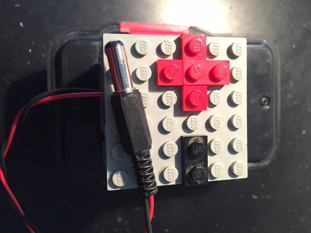
For the battery, I made an adapter out of LEGO. It fits over the part that normally slides into the drill, and makes the electrical connections. The LEGO part is very easy to make. You just need to add 2 small pieces of metal, that make contact with the terminals on the battery. Next, solder 2 wires to it, and connect them to a barrel jack (center positive). This goes inside the plug on the perfboard. The assembly fits perfectly in the box we made earlier.
(Make this piece first and adjust the dimension of the box to its size.)
Lastly, add some isolation foam to the lid of the trunk, and in the part of the box where the battery sits. I also made a small cutout for the 9V battery and the remote control.
Add the wires and battery charger, and the work is done!
Step 5: Test and Enjoy!


The wireless igniter is now finished and should be fully functioning!
To operate, simply connect the battery and the wires. For attaching the fireworks, put the fuse through the loop of NiCr wire and hold it with the crocodile clip, like shown in the picture. Turn on the power switch (the green LED should light up) and WAIT. The small blue LED should blink 3 times, which indicates the arduino is running the program. If the red LED is on, something is not working, and the key switch may not be turned (check if the wires are correctly inserted)! If the red LED is off, you can safely turn the key switch on. Attach the IR receiver outside the trunk, and close the lid.
Take some distance and press a button on the remote control. The blue LED should blink once, and your firework should light (the range is about 15-20m)! Press the next button and enjoy your work. :)


