

Introduction: ZIF Attiny "Arduino As ISP" Programmer With External Clock


Tired of having to carefully insert and remove your Attiny84 or 85 from the jaws of a dip socket, risking with every pull the possibility of bending the legs beyond straightening or worse, tearing them clean off?! If so, this instructable is for you! Cheesy sales pitch aside, this setup allows you to easily and safely program an Attiny45/85/44/84 with the ability to use an external clock if necessary!
Step 1: Gather Your Ingredients
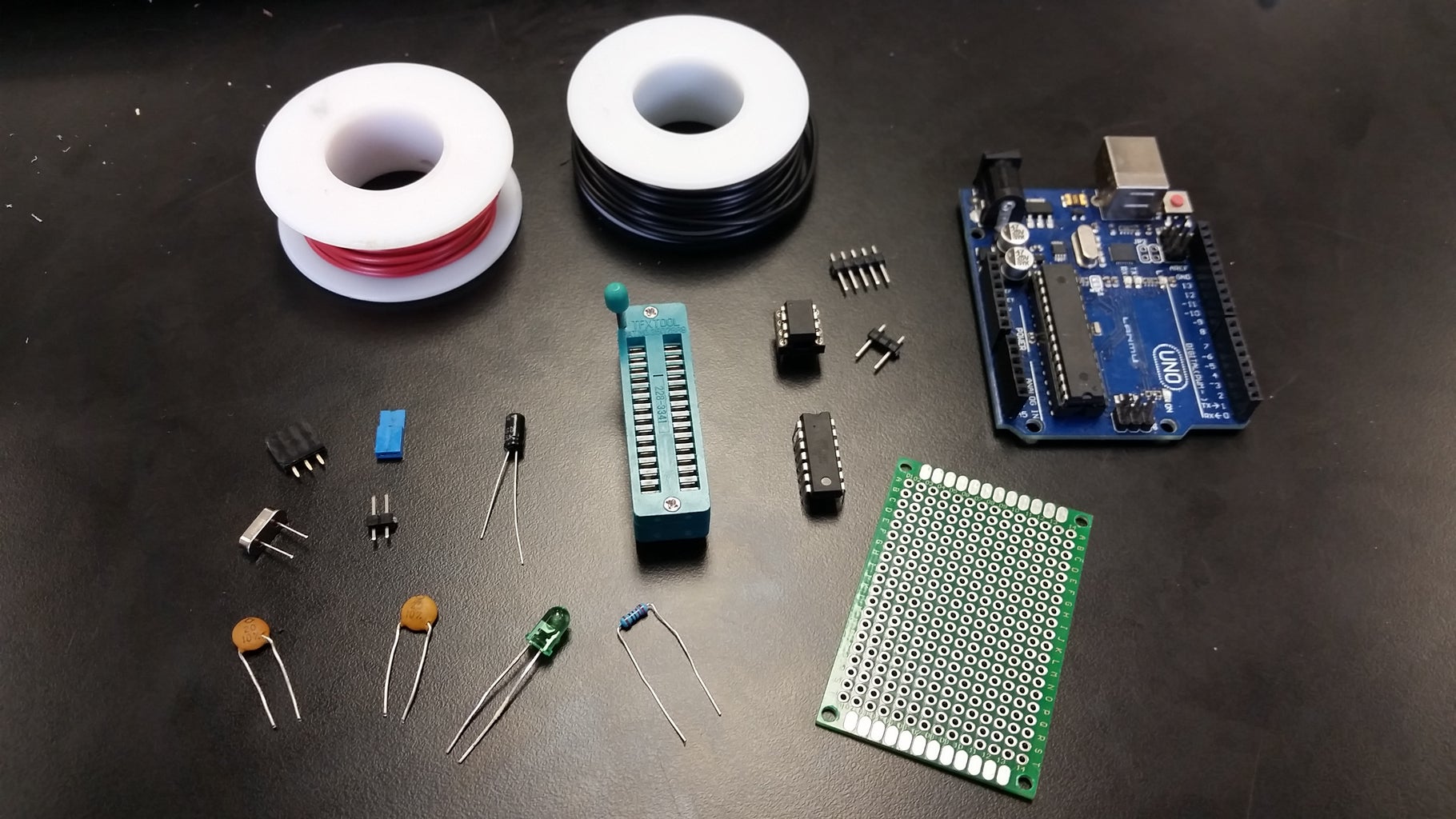
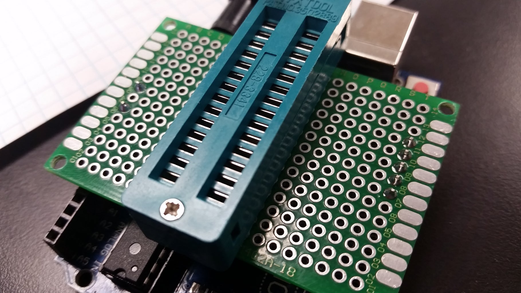
This project will take a fair amount of components. Chief among them is the ZIF (Zero Insertion Force) DIP (dual in-line pin) socket, which allows you to easily and safely switch out chips without the risk of damaging the frail legs. Here is the list of all of the components:
- Arduino Uno board to use as the ISP (In System Programming) programmer.
- 4cm x 6cm Protoboard (I prefer the double sided type).
- Male and female headers.
- 28 pin ZIF DIP socket.
- LED and current limiting resistor (220 ohm in this case).
- 2x 22pF ceramic capacitors (I used 20pF).
- 10uF electrolytic capacitor.
- 22 or 24 AWG solid copper wire
- Attiny85/84
NOTE: I initially thought that I would need a jumper to decouple the capacitors from ground when the internal clock was being used but it turned out to not be important, therefore, you will not need the jumper as seen in the picture.
Step 2: Set Up Your Arduino to Be the ISP Programmer

First thing to do is plug in your Arduino Uno and navigate to the "Arduino as ISP" sketch located under examples. File -> Examples -> ArduinoISP -> ArduinoISP Make sure that under Tools -> Board, "Arduino/Genuino Uno" is selected and Tools -> Programmer is set to "AVRISP mkll" otherwise you will get errors! Once all that is set, click "Upload" and your board should now be setup as an ISP programmer!
Step 3: Let's Figure Out What Needs to Go Where


On the Arduino Uno board, the pins we'll need on the left side (when oriented as seen the picture) are:
- Reset
- 5v
- Ground
and on the right side:
- 10
- 11
- 12
- 13
- If needed, Ground
Now, we need to look at the pins we'll need on the Attiny's. On the unofficial Attiny pinout image, you can see all of the functions of all of the pins; a great reference to have. For ISP programming, we'll need the pins corresponding to SCK, MISO, MOSI, and Reset (SCK: Serial Clock; MISO: Master-In, Serial-Out; MOSI: Master-Out, Serial-In).
Attiny45/85:
- SCK: Package Pin 7
- MISO: 6
- MOSI: 5
- Reset: 1
Attiny44/84:
- SCK: 9
- MISO: 8
- MOSI: 7
- Reset: 4
Now we need to line those up with the corresponding pins on the Arduino so:
Attiny45/85 -> Arduino:
- SCK: 7 -> 13
- MISO: 6 -> 12
- MOSI: 5 -> 11
- Reset: 1 -> 10
Attiny44/84 -> Arduino:
- SCK: 9 -> 13
- MISO: 8 -> 12
- MOSI: 7 -> 11
- Reset 4 ->10
Also, we'll tack the LED to the Attiny's SCK pins so that we may watch the clock pulses fly by during programming and then have a way to test the tiny's to make sure they are bootloaded and operating correctly. Finally, we need to find out which pins correspond to the external clock crystal (Skip this part if you only plan to only use the internal oscillator with your tiny's!). According to our unofficial guide the XTAL (CrysTAL) pins are fortunately:
Attiny44/84/45/85:
- XTAL1: Package Pin 2
- XTAL2: 3
Note: This XTAL is independent and different than the one on the Arduino, therefore, there will be no direct connection between it and the Arduino.
One last connection to be aware of is the 10uF electrolytic capacitor that needs to be connected between the Reset pin on the Arduino and ground to prevent the Arduino from resetting during the programming of an Attiny.
The image with my chicken scratch has a summary of the necessary connections.
Step 4: Let's Think About It, Then Make a Schematic!

It's is very helpful and often a necessity to first create a schematic of your proposed circuit before beginning construction. Reason being, as your circuit becomes more complicated, a schematic helps find errors in connections before you spend hours laboring over the protoboard. Also, it helps you get all of your ideas out in a clear manner and may even spawn new or more efficient methods to your circuit. Above all, it gives you something to refer to as you are assembling and just looks really cool :). The plan here is to wire the ZIF so that all of the important connections (SCK, MISO, XTAL, etc.) are in parallel. As an immediate consequence, you will not be able to program the chips simultaneously (if you needed to for some reason) simply because the software requires you to specify exactly which chip you are uploading a sketch to. That shouldn't be a problem, just something to be aware of. Next thing we need to keep in mind is marking the ZIF socket to indicate which tiny goes where to make sure all the right connections are made. I chose the Attiny45/85 to sit up front with package pin 1 in the top left corner by the locking lever. Now that we have that taken care of, you can use a program to design the schematic or break out the the ruler and graph paper and sketch it out the old fashioned way, I typically choose the latter as it brings more satisfaction, but to each their own!
Step 5: Layout the Circuit Board


This part is also very important to make your life less painful while making the connections. A few things to keep in mind is to place components as close to the headers they connect to as possible and direct legs that connect to ground near the outer perimeter of the PCB so that you can easily connect all the grounds in a linear fashion to prevent ground loops and likewise for the positive line. Once you are comfortable and satisfied with the placements, the fun part can begin!
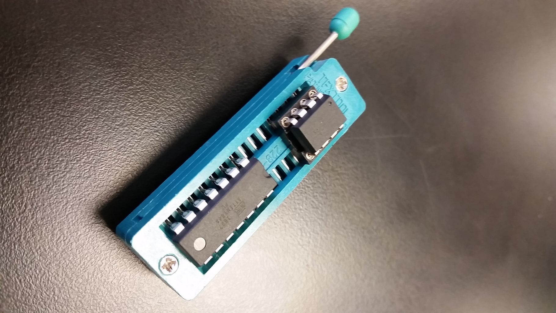
Step 6: Start Soldering! But Take Your Time.
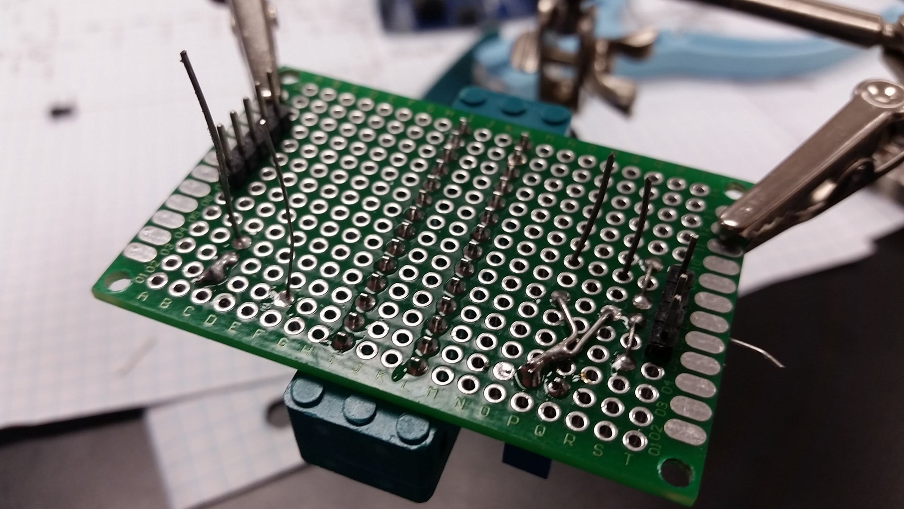
I suggest soldering the ZIF socket first since it is front and center, then populate the surrounding area with other components, small first. Be sure to fully heat the leads to combat cold welds, but also don't overheat the components (do you want me to tell you how to tie your shoes too??). Be patient and logical to prevent errors and minimize troubleshooting time.
Step 7: Double Check Your Connections
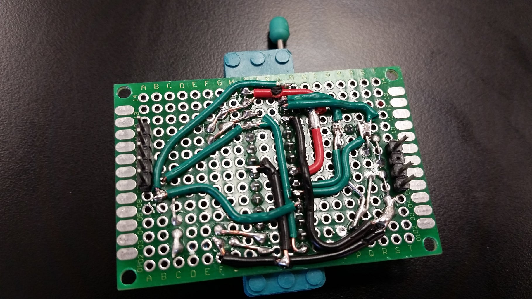
As you can see, there are a lot of connections to be made and therefore a lot of potential problems. Check solder mounds that are close together because sometimes they can leak into one another during soldering. This happened to me so I just to a sharp razor blade and carefully ran it between the two mounds a few times until I was reasonable sure they weren't touching anymore (you could use a continuity tester to confirm). In general try not to overlap wires unless absolutely necessary. This will make adjustments easier and make it look better/well thought out(looks are important ya know!).
Step 8: Test It!
Now the moment we've all been waiting for! Go ahead and mount your fresh PCB, lock down your Attiny and plug in your Arduino to your computer, but before you upload the test sketch, you have to make sure the settings are correct! If you have never programmed an Attiny with your IDE, then follow these steps, if you have then just skip to uploading the test sketch.
- Make sure you have the most up to date Arduino IDE (1.8.1 in my case).
- Go to File -> Preferences and copy and paste this URL into the "Additional Boards Manager URL" box:
- Then click "Okay" and navigate to Tools -> Boards -> Boards Manager.
- Type in "attiny" into the search bar and install the most recent version.
- Click "Close" and go to Tools -> Boards and carefully scroll all of the way to the bottom and select your Attiny board.
- Now select Tools -> Processor and choose your specific Attiny.
- Select your clock Tools -> Clock -> Internal 8 MHz
- Ensure your Arduino board is recognized Tools -> Port and click on your device
- This next step is very important! Tools -> Programmer -> Arduino as ISP
- Now, if this is a new Attiny and you are unsure if the bootloader (a bit of code used to establish connection with a computer upon restart of the microprocessor) then select Tools -> Burn Bootloader
- If all went well, and no errors received, then at the bottom left corner of the IDE, you should see "Done Burning Bootloader".
Now, set the ledPin to its correct value and upload this sketch (in between the asterisks) :
*****************
int ledPin = 0; // ATTINY45/85: D0 ATTINY44/84: D6
int onTime = 1000;
int offTime = 1000;
void setup() {
pinMode(ledPin, OUTPUT); //Declare ledPin as an Output
}
void loop() {
digitalWrite(ledPin, LOW); // turn the LED on
delay(onTime);
digitalWrite(ledPin, HIGH); // turn the LED off
delay(offTime);
}
******************
NOTE: The given ledPin assignments are if you place the LED on the SCK pin, otherwise you'll have to change it accordingly!
If your LED starts blinking, then you are good to go!!!!
Now that everything is operating properly, if you chose to add the external XTAL option, then go ahead and install your crystal of choice, change the clock setting under Tools -> Clock -> External xxMHz, then re-upload the sketch and your LED should start blinking! To prove the Attiny is running off of the external XTAL, remove the crystal from its header socket and the LED should stop blinking, either staying HIGH or LOW depending on what state is was in the moment you removed the crystal. That should be all to get you started but if unfortunately, it isn't working as planned, I will go over some of the issues I had and how they were fixed.
Step 9: Troubleshooting
In the event of your newly made device not working as planned the first time (more often than not), comes the task of troubleshooting. Here we will walk through the basic steps to try and narrow down where something may have gone astray. First, we'll discuss hardware issues, then we'll move to software.
Hardware:
If while you are attempting to upload to the Attiny and you are receiving errors in the IDE, the first thing to do is remove the Attiny but leave the Arduino plugged into your computer. Next, assuming you have one, take a multimeter and find good ground point on your PCB or Arduino to clip or firmly hold the negative probe to. Then, take the positive probe and touch the holes on the ZIF socket where you know there should be positive voltage for the Attiny's, if you get close to 5 Volts, then you are good. If not, then trace back all of the connection points along the poitive line until you get back to the Arduino board, you should locate the error. If everything looks good but you still have 0 Volts, then try a different ground point.
Likewise, it is possible to have a poor ground on your PCB so clip or hold the probe at a known 5 Volt location and with the negative lead of your multimeter, check all known ground points and ensure that they are "active". (This can be somewhat misleading because a point that's supposed to be ground the same 0 Volts reading as some other disconnected point, but the main point of this exercise is for you to carefully examine and cross check connections with the schematic)
Hopefully now you will have voltage and ground at every point you need it. However, if you are still receiving errors while uploading, then we'll need to use some context clues.
If the sketch fails to upload immediately, it usually is a software or setting issue. If the upload will start and then stall a second or two later, it points towards the Arduino -> PCB -> Attiny. Now we'll assume this second scenario and watch the Arduino board carefully after we click upload. If you recall that during a normal upload to an Arduino (not configured as ISP), the onboard LEDs blink in a somewhat regular fashion during the upload. The same sort of quasi-predictable flashing occurs while uploading to the Attiny. Therefore we should see blinking of the Arduino's onboard LED. If we do not, or if the behavior is strange then it tells us the problem is located not in the Software/settings, not on the Arduino itself, but up on the PCB board. If the onboard LED begins to blink and then gets hung up and kind of fades and dims during upload, then this indicates a short somewhere on the PCB. Earlier I mentioned ensuring the solder mounds were all independent for that can cause a short but another less evident cause can be the melting of the wire insulation due to exessive heat while soldering. If the insulation of two wires are touching, either running parallel to or lying on top of one another, the extreme heat from the soldering iron can cause the insulation to melt enough for the conductors to touch and cause a short. This short is reflected by the dimming of the onboard LED as current is being redirected through the path of least resistance.
Another important component to check is the 10uF electrolytic capacitor. This should be strung between the Reset pin of the Arduino and ground. If the connection is not solid, then the Arduino has a tendency to reset itself during upload of the Attiny sketch, causing errors.
Finally, if you can successfully upload your sketch but you don't see the LED blinking, then simply check to make sure you are assigning the right pin (Note: the physical pin number is often different than the pin number in the software so double check with the unofficial pinout chart!!) and that the LED is connected properly, that is, the LED is forward biased.
The following error I received while trying to upload to an Attiny84. I had just successfully uploaded to an Attiny85 so since all of the pins are in parallel, I assumed the 84 should upload without a hitch. Unfortunately that was not the case, and it turned out that I had connected the Attiny84 pin 10 -> Arduino 10, instead of Attiny84 Reset pin 4 -> Arduino pin 10, a simple overlook while assembling. But if you receive this error, check your pin connections!
avrdude: yikes invalid device signature
Software:
If the upload fails immediately after clicking "Upload", then more than likely, the issue is software related. That is, with the IDE, your sketch, or a connection issue. The solution of these issues depend largely on what avrdude tells you but a few hints and places to check are:
Check to make sure you computer and the Arduino IDE recognizes and will connect to your Arduino Tools -> Port -> Your Arduino. If not, switch out your USB cable with a known working one to rule that out.
Ensure you have selected the correct Board, Processor, Clock, Port, and Programmer.
In the end, the most effective way to solve software issues is to search the issue using your favorite search engine like http://www.duckduckgo.com (shameless plug) and see if others have had that same issue (more than likely) and how they fixed it.
Step 10: Conclusion

This project served as an upgrade to the simple Attiny programmer that one cannot go wrong with. But if you plan on getting into projects that use the Attiny45/85/44/84, it is beneficial to have a single programmer that can accommodate the different number of pins and clock speeds. If you have any questions, concerns, criticisms, or suggestions please don't hesistate to comment or PM!
Pro Tip: When pushing down the lever to lock an Attiny in the ZIF, hold down on the opposite side of ZIF to prevent putting pressure on the Arduino side headers/headers on your PCB. This'll ensure a long and productive life of your Attiny "Arduino as ISP" all-in-one ZIF programmer!
Stay tuned for a future project constucting a ZIF programmer for an Atmel Atmega328p (the chip Arduino's use) using an FTD1232 ISP chip and header for true insystem programming for stand-alone operation!
Step 11: Further Reading
Talking about the relationship between Vcc and clock speeds:
https://www.avrprogrammers.com/attiny/attinyx5?dev...
Setting up the IDE to program Attiny's:


