

Introduction: ZIF Jig for AVR ATtiny Chip Programming


I bought a couple of AVR programmers from e-bay, knowing that I would need to build a jig to connect my ATtiny85 or ATtiny13A. I wanted the jig to use a ZIF (Zero Insertion Force Socket) for my chip, and connect to programmers that use either a 6 pin or a 10 pin cable.
The key to assembly is a Schmart Board. It holds the ZIF socket, header pins for either format cable, a reset button, and two LEDs. Schmartboards are actually quite easy to solder.
The first LED (green, next to ZIF pin 1) is lit when power is provided to chip to be programmed. Some programmers have options to not send power over the cable, so it's useful to notice an un-powered chip!
The second LED is a tri-color Red+Yellow=Green. It's hooked to chip pins 2 (PB3) and 3 (PB4). When I first get a chip, I program it with a Binkey variant which flashes these pins.
Finally, right next to the ZIF handle is a female 6 pin header for my special bonus.
Step 1: Extra Added Bonus -- Onboard Programmer!


Doing my layout, I saw there was space for connecting my micro-programmer directly to the jig without a cable!
Right next to the ZIF handle I added a female 6 pin header that accepts the on-board programmer. I took my micro-programmer (it came with the pins loose) and soldered them pointing downward instead of upward.
(If I had some super-super long pins, I would have soldered them through to point both up and down {frowny face}.)
The first picture shows the FabISP micro programmer installed. It's functionally equivalent (I believe) to the USBtiny ISP.
The other pictures show the pins. The big black blob is the plastic end-cap from a shelving unit glued on with GO2. I ground away at it until it was sized to provide support for the programmer at its installed height.
Step 2: Materials


Schmart Board 201-0001-01 $5+unknown shipping. Mouser $5+$7 shipping. Jameco and Digikey seem to have stopped carrying them.
ZIF socket e-bay $1 (Shorter ones exists; you only need 8 pins.)
Male header double row e-bay 2/$1 (Get 40x lengths of "snapable" and break off pieces.)
Female header single row e-bay 3/$1 (Ditto. See below.)
Tactile Switch e-bay 10/$1
Green LED size T1 (about 5/32" diameter) (my junk box)
680 ohm resistor 1/4 watt (my stock). You might want to experiment with this value to get the brightness you want.
Tri-color LED Kingbright WP59SURKCGKW Digikey 754-1886-ND $.60 10/$4.31 + $3.50 USPS postage. Unpedigreed from e-bay $1.
470 ohm resistor 1/4 watt (my stock).
Hookup wire, 6 or 7 colors (my stock). 26 AWG (American Wire Gauge) is fine; 22 gauge may be slightly more difficult to work with. If you have some Cat5 cable, hack off a foot or so and untwist the 4 pairs. Scrounge Red and Black for power, perhaps from some telephone cable.
(All prices are USD July 2017 and e-bay prices include free shipping.)
Alternatives:
Substitute an IDC (Insulation Displacement Connector) box connectors for the male headers. It has a key to keep the cable from the programmer inserted correctly.
10-pin (2x5) box connector e-bay $1. 6-pin (2x3) box connector e-bay $5. You might make a 6 pin out of a 10 pin by clipping out a pair of pins on each side, leaving the center 6.
Resistors and the Tri-color:
First, you can just as easily use two unique LEDs from your junk box. The only thing special about the tri-color is its coolness as a single bulb changing color. There is one resistor on the common cathode (minus). If you don't like the shade of yellow when both sides are turned on, you will have to remove the cathode resistor and put a resistor on each anode with values chosen to delight your own eye.
Female Header:
The double row ones I had in my stock were 0.1" pin spacing in each row. However, the rows were spaced 0.145" apart, so they would not line up with the holes. My quick fix was to use two singles side against side to get a 2x3 connector. See the photo where they are clamped together...
E-Baying:
If you go e-baying, check the fine print for the sizes. Many sellers don't know how their products are used or normally specified, so they don't always put this sort of essential information into the listing.
I've found the possibility of getting several different parts from the same vendor to save on shipping is very hard. Very few people who provide "free shipping" will quote a combined order, and no one seller seems to have everything you want when you need more than a few items.
When ordering multiples of the same item, look for listings of "n pieces" or "nX" further down the results rather than ordering quantity "n" of a single item.
Step 3: The Magic Schmartboard


The key to putting so much on a small board is using a Schmart Board.
It has two layouts with 0.1" centers superimposed at a 0.07" diagonal offset. You can put 3 lines of connectors, sockets, or double row components across the board, and with careful layout, put another 3 lines on the offset layout.
It's also much easier to solder than you might think -- the resist strongly encourages the solder to stay with each plate-through hole and not jump next door.
All holes are plate-through. Most holes are connected in a trace of 5. The four corners have traces of 3 holes labeled "GND" -- all grounds connect internally to each other. There are also four traces of 6 holes on the sides of the board that can be used for general distribution.
In the red photo, you want to rotate the board counter-clockwise so the edge with a zillion holes is at the bottom. Then it will match the other two photos. They are solid and outline maps of each trace.
Getting the components positioned correctly is the most difficult thing in this project.
Misalign by 0.07" and you will be on the wrong trace, which may have a different component connected to it. Now you have the two parts inadvertently connected. {teary face}
This project is designed so that no component shares a trace with any other component. Study the board carefully after you have them all placed, looking hard for any trace with two or more leads!
Finally,some painter's tape can be useful to hold headers in place when you do component placement. You really want to be looking at the back side of the board where the traces are printed without have to catch the headers as they fall...
Step 4: Schematic and Diagrams


First, print diagrams and picture.
Second, always keep track of where pin 1 is on the picture and on the board. Spin the pictures around to keep them orientated with the board as you work.
Third, remember that the ZIF socket is numbered differently -- the pins go counterclockwise around, so 8 is opposite 1, and 5 is opposite 4. The ATtiny13 and ATtiny85 have similar pinouts, so both will work in the jig.
Lastly, use a different color wire for each of the six signals. MOSI and MISO are very easy to confuse. If you only have three colors, assign 2 of them to these signals. Label the diagrams with your wire color choices!
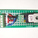
The image with the colored dot and outlines of the Schmart Board traces is the bottom side view. It shows where the pins of each component go, and where the jumpers go. All components are placed on the top side, with the pins sticking though where the dots are.
Turquoise is the ZIF socket -- I don't solder all the pins, just what's used, plus some to hold the other end.
Sky Blue is the header pins. The two sets together are male (bare pins) and the one closest to the ZIF is female. Note the female is the on the offset layout from the ZIF socket, otherwise it would connect to the same trace as a couple of the ZIF pins.
Yellow are the LEDs, resistors, and switch. The 680 ohm goes next to the 10-pin. The 470 ohm is at the edge, between the ZIF and the tri-color LED. The green LED is in the corner. The dotted lines indicate these are on the opposite side of the board so that you will only see their leads sticking though from the top.
Purple are jumpers, which have solid lines connecting the holes to indicate they are pieces of stripped wire.
The photograph is the Schmart Board top side view, hopefully with enough resolution for you to count the holes.
Step 5: A Word About Soldering.

All the wiring can be done on the bottom of the board, with the end of each wire just poking into a hole.
Use a very fine pointed tip on your iron, no wider than a hole. Flux isn't essential, but you may need it if your wire is old. Unfortunately, flux core solder in thin gauges is very skimpy -- a flux pen is a wonderful tool if things aren't very clean.
Strip off 3/16" of insulation, and stick the wire into the hole so that some of the bare part is still visible. Hold the solder against the bare wire and the rim of the hole, then touch them together with the iron. You will see when things heat up enough to wick some solder into the hole as well as coat the wire.
Go light with the solder. If the joint seems dry, come back and add more solder. While you don't want to heat things up more/longer than necessary, headers and sockets can take a lot.
If you accidentally bridge two hole, clean off the soldering iron tip, the touch each hole in turn. Come in from above and aim for the center. The melted solder may roll off the resist and return to the rim of the hole. If that doesn't work, get out the solder wick (copper braid with wetting agent) and sop up as much solder as you can. Then repeat the hole-touch maneuver.
If a hole gets plugged and you don't have a de-soldering pump, try pressing a dress maker's pin against the center of the hole, then the iron again the the pin and rim together. Downward pressure on the pin may push the solder through, leaving a lot adhered to the pin. A baby diaper pin used as a ream can push solder back to the rim and widen the hole a bit. And of course, solder wick is your friend!
Step 6: Place Basic Components


The photo is a smart board with two male headers, the ZIF socket, and the green power LED and its resistor. That's everything needed to connect a chip to a programmer.
The headers and the ZIF socket will all be on traces that are directly above each other. When the socket and headers are in the board, a ruler straight edge will touch every pin in a horizontal or vertical row. If a row seems to slightly ziz-zag, you have something 0.07" "high and wide", or "low and below".
Note that each header row pin is at the end of a trace, and there is a gap between the traces at every pair of pins. If you are a row too high or low, then vertical pairs of pins will be connected on the same trace and that won't work!
The green LED and vertical resistor on the left edge use the same trace layout as the header/ZIF pins.
1. Orient the Schmartboard. The bottom is the side with the most holes (almost twice as any other edge). The back side has traces (lines connecting many of the holes together); the front side is exactly the same shade of green between all the holes. Use a bright light and tilt the board back and forth until you're sure which side is which.
Start with the board front side up, bottom edge closest to you. Consult the front side picture above.
2. Place the ZIF socket. At the bottom right an left sides is a trace of 3 holes labeled "GND". The bottom row of ZIF pins go on a line connecting the top most GND pin of the trace. It is the third hole up from the bottom on each edge.
The 28 pin ZIF socket should fit neatly with the side edges of the Schmart Board. The handle is on the right. There are (barely) two rows of holes visible between the bottom of the ZIF and the bottom of the board.
Verify that the ZIF is on the side of the board without any traces. Flip the lever up, turn the board over, and then tack it down. I suggest soldering pins 1 and 15 (opposite corners), then pins 14 and 28. Keep the socket cool; Chinese plastic can warp a bit and mess up the alignment of the tabs. Always waiting for things to cool between each pin, do the other 3 pairs on the end away from the ZIF handle.
3. Place the male headers. Every pin sets at the end of a separate trace. Header pins are in the same columns as the ZIF pins. Use a straight edge to verify every pin is in a straight line with other pins, and are not off by 0.07". Check both vertically and horizontally.
Solder down the headers, going in circles between headers allowing things to cool off before an adjacent pin is soldered.
4. Stick the LED with the short lead (cathode) into a hole in the GND trace at the lower left of the board, and the long lead in the next hole over (0.1") to the right. It will be a trace running vertical under the ZIP socket. Solder the LED. A small pair of forceps can hold both leads of the LED on top of the board, acting as a heat sink while you solder on the bottom side.
Insert the vertical 680 ohm resistor vertically along the very edge of the board opposite the ZIF lever. It should bridge the spot where there is no hole. Solder it in.
Step 7: Place Optional Components


The optional components are all on the alternate or offset layout. None of the traces they connect to are used by the basic components. For example, you will see the traces for the female header run between the traces for the ZIF socket.
You have two choices with the optional components:
Bonus micro programmer:
1. The onboard micro programmer needs the female header. It is two 1x3 pieces side by side running horizontally. It is close to the ZIF lever, and sets next to the "missing hole" at the middle of the edge. Note that each pin connects to a unique trace, just like the male headers. Solder them in.
Reset switch, tri-color LED, and its resistor for running a Blinky test program.
1. Place the switch. You will probably have to adjust the legs to match up with the holes. Watch it, as it will want to move "out of level" while you're handling the board. Its horizontal position is critical, as the left side trace will be jumpered to connect with another trace reaching ground.
Get out the continuity checker and verify the left and right sides are NOT connected. It's really easy to get the switch rotated 90 degrees... Re-check that the switch is pressed down and level as you solder the 4 pins.
2. Run a 470 ohm resistor immediately below the 10-pin socket. One end goes in the trace with the left side of the switch (ground). The other end goes to almost the middle of the 10-pin socket, stopping on a trace which runs between the traces where the header pins connect. Solder it in.
3. Insert the tri-color LED. The center pin will be in the same (vertical) trace as the horizontal resistor. If you use your own LED(s), you want your cathode (minus) short lead(s) connected to the resistor. Use forceps for a heat sink when you solder the LED.
Step 8: Wiring Pass 1: Power and Ground Jumpers


Warning: The hairpin jumper is off by 1 row in the pictures.
The 10-pin header has power at pin 2, and ground at pins 4, 6, 8, and 10.
We do this step first because there is only 1 free hole on the 10-pin header #2 trace that aligns with a 6-hole side trace. Fill it now, and you won't use it latter while daisy chaining.
Cut six bare wire jumpers with 0.1" between the legs and one with 0.2" between the legs. Make each leg very short, maybe .07" long, and put an arch between the legs so the jumper won't solder-bridge to the alternate trace(s) underneath. Finally, cut a hairpin jumper about 0.07" between the legs.
When you solder in a jumper, keep it slightly high so it doesn't touch the trace(s) underneath it. Put some painter's tape on the top side of the board where the jumper would stick through. This will help keep them elevated. A pointed tooth pick under the arch can help hold the jumper up if you're worried.
Work on the back side of the board, because one jumper sets on top of the ZIF socket, and for aesthetics, and so you can see the traces.
1. Go to the very corner of the board nearest the 10-pin header. It's opposite the ZIF socket and the same side as the green power LED. There is a 3 hole trace labeled "GND" ending with the corner hole. The long jumper goes in that hole and the one 0.2" (2 traces) directly on the edge of the board. It is at the end of the trace containing pin 4 of the 10-pin header.
2. All ground pins for the 10-pin header need to be jumpered together, (4-6, 6-8, 8-10). Keep going and connect pin 10 to next trace, where pin 12 would be if the header had that many pins. (This trace carries ground up to the tri-color LED resistor).
3. Still in that corner, follow the 3 hole GND trace up the edge of the board to the next (6 hole) trace. The bottom hole of this trace (next to the top hole of the GND trace) gets jumpered to the hole directly in-board, which has pin 2 of the 10-pin header.
4. Follow the 6 hole trace up the side of the board, cross the gap with the resistor and continue along the other 6 hole trace that goes under the ZIF socket. Place a jumper between the end hole and the hole directly in-board, which is on the trace that ends at the green LED anode (positive) pin.
5. Finally is the 0.07" jumper which connects the trace for the left side of the switch to the ground trace beside the 10-pin header. It is inserted diagonally between adjacent traces, one in the primary layout and the other in the secondary layout. Connect the last hole in the trace for the left hand side of the switch and the last hole in the trace for "virtual pin 12" of the 10-pin header (which step 2 jumpered to ground earlier). Solder-bridge the two traces.
Now is a good time to clean the board (paint thinner & tooth brush) as there are no wires yet.
Take a break, take a nap, come back tomorrow. Then visually inspect the board with a magnifying glass. Compare it against the printouts to verify every lead/jumper is in exactly the right hole. Find and do needed solder rework.
Step 9: Wiring Pass 2: Programmer Signals


The same six signals appear on all headers and the ZIF socket.
Pick one, grab the assigned wire color, and daisy chain up the headers and ZIF socket. If you didn't write down the color you chose on all the pins on all the diagrams, do it now. Saves tears later.
Repeat for the other 5 signals.
1. Keep the diagram and board oriented with each other while you work.
2. Pin one is always on the corner nearest the green power LED.
3. Treat the ZIF socket holding the chip as being numbered the same as the chip that will be inserted into it. For ATtiny, pins 1 to 8 go counterclockwise so pin 5 is opposite pin 4, and 8 is opposite 1.
4. Don't confuse MISO on 6-pin header pin 1 with MOSI on 10-pin header pin 1.
Color code in the photos:
White - MISO
Orange - SCK
Green - Reset
Blue - MOSI
Red - Vcc (positive power)
Black - Ground
If all you need is the ZIF socket, you're done (Skip on to the Verify step.)
Step 10: Wiring Pass 3: Optional Components
Bonus micro programmer:
If you added the female header, you already wired it during the daisy chaining step.
Reset switch, tri-color LED, and its resistor for running a Blinky test program.
Now before you run off and make a design change by connecting a LED to another pin than 2 or 3, remember that all the other chip pins are carrying programming signals like MOSI, MISO, and SCK. If you connect a LED to any of them, you will pull down the SPI bus signal lines which will hinder communications with the programmer.
Connect one side of the tri-color LED to ZIF socket pin 2, and the other side to ZIF socket pin 3. Or, your connect your LED(s) anode(s) if you don't use the tri-color LED.
Step 11: Verification.


1. Get out the continuity tester and check the daisy chaining. Again, verify the orientation of the headers against the signal names on the diagrams. Remember that the 10-pin connector has 4 ground pins.
I replaced one probe with an alligator clip lead attached to a male/male jumper, and moved the jumper through each of the 6 pins on the female 6-pin header. The other lead was the standard probe to touch the ZIF socket and other header pins.
2. After you're testing the reset chain, leave the tester connected to the reset pin and ground the other probe. Push the button and see/hear the connection.
3. Verify the LEDs. I just connected my 5 volt power supply* ground to a board ground pin, and touched the +5 volt lead to a header Vcc pin to flash the green power LED. Then I touched the lead to ZIF socket pin 2 to display one color, ZIF socket pin 3 to display the other color, and then both pins 2 and 3 to display the combined color. BTW, it seemed more orange-ey than yellow.
Finally, put away your power supply and continuity tester. Put a chip in the socket and hook up your programmer.
The (Khazama) GUI supports the USBasp programmer that I have, which uses the 10-pin connecter. It has a read chip data option. I tried it first, and it pulled data from a virgin ATtiny13A to my great delight.
The AVRDUDESS GUI supports the micro USBtinyISP programmer., which plugs into the female header. It's basically a command line generator to invoke AVRDUDE.
* The Diode Check function on my multi meter will light the LEDs, when connected in the correct direction. A battery pack good for 3 volts or more should work too...


