

Introduction: Full Colour Moodlamp on a Concrete Base


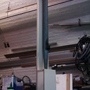
An adjustable full colour moodlamp with a cast concrete base. The organic form of the lamp is made by putting a large lycra sock over 2 aluminium rods that are bent over and held by embedded tubes in the base.
The bulk of this instructable is about creating the concrete base. There isn't much on the electronics - as there is so much already out there about using micros and LEDs.
Step 1: Making the Mould


- be heavy,
- have adjustable feet,
- have recessed panels for the controls and power,
- have integrated tubes that will accept the aluminium loops for the fabric form.
Tubes for the aluminium supports were held in place with short lengths of the aluminium rod (also keeps the concrete out). Nuts for the front panels and LED plate were also cast into the concrete.
Step 2: Pouring the Concrete

Mix the concrete according to your bag's instructions. I didn't use gravel, just sand and cement. Pour a little at a time and then agitate with a stick.
After pouring all the concrete, knock out the air bubbles with gentle hammer taps on the outside of the mould. I also tried vibrating the mould with an electric sander - but didn't notice much more bubbles appearing.
This step is important because otherwise the bubbles could make the finished piece look bad, or if a bubble was in an important place it could cause problems with mounting the plates.
Step 3: Inspecting the Cast


- tubes exposed for the fabric support loops
- central hole for reducing weight
- recessed front (and back) panels for controls/power
- recessed nuts for screwing led support panel
- I tapped the tubes so the screw in feet could be adjustable height for stability on uneven floors.
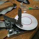
Step 4: Electronics

the electronics is based on an Atmel AVR mega 88. Overkill for this project but I had some hanging about. The LEDs are high power 3 colour clusters. I used 2, so needed transistors to switch about 500mA each.
I didn't use a crystal, because I didn't need good timing - I used the on board RC oscillator.
I exposed the in circuit programming header on a parallel port connector for easy reprogramming.
The software is written in C, and will be available here soon. It reads 3 variable resistors for the controls and then writes PWM values to the transistors.
There are seven programs, selected by the right hand knob. The middle knob is intensity. For colour cycle programs the left knob is speed. For the colour creator program, the left knob is hue.
Step 5: Fitting the Hardware


Next step we add the front plate (with electronics behind), the rear plate and the LED plate.
Step 6: Fabric Form


I put 2 long pieces of 3mm aluminium rod between the tubes in the base. Then I put a large sock made of lycra over the whole piece to create the form of the lamp. The aluminium can easily be bent and changed to alter the volume created by the lycra sock.
Step 7: Finished Photos


here are some photos to show the final lamp


