

Introduction: 3D Laser Cut Lamp


This is a tutorial on making a 3D object out of 2D Shapes in Fusion 360. If you follow along, you'll be well on your way to designing and making complex 3D designs using any method of 2D panel fabrication.
No laser cutter? No problem. Just follow my Digital Fabrication by Hand instructable and you can make all kinds of complex designs using a jigsaw and a hand drill.
Before we get started, download the Ikea Cord Set.f3d model from this step. The cord set is available on the company's website for $5.
To import the model, open the Data Panel and select (or create) a Project from the list. Next, click the Upload icon in the Data Panel on the left of the Fusion window. Drag the file onto the window that pops up, and the model will now be on the cloud and ready to use.
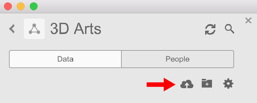
Upload cord set file
Attachments

Step 1: Fusion 360

Autodesk Fusion 360 (free)
This is a powerful 3D modeling platform that's easy to learn but has endless potential. With it, you can design complex 3D objects for practically any kind of fabrication, digital or otherwise.

Click here to sign up for free as a Hobbyist / Enthusiast / Startup or as a Student or Educator.
- Follow one of the links above to download the app (don't use the App Store on Mac).
- Enter your email and download the free trial.
- Install and setup a free Autodesk ID account.
- When you open Fusion, select the Trial Counter in the upper toolbar (it tells you how many days are left on your trial).
- In the next dialog box, select "Register for Free Use".
- Sign up as a Start-Up or Enthusiast (Free). You can also Sign up as a Student or Educator (Free) if you're a student or educator at a registered institution.
- Select the "I accept Terms and Conditions" checkbox and click Submit.
A browser-only version is in the works, but hasn't been released yet. It's in beta right now, but check this link after November 15 for an announcement about a release date: Project Leopard
Step 2: Place Cord Set Model
When you open Fusion 360, it automatically gives you an "Untitled" blank file to work with. You need to insert the Ikea Cord Set file, so first you need to save the "Untitled" design and give it a unique name.
Insert cord set model
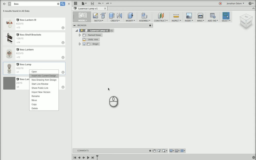
Now that you've got a saved file, you can right-click on the Ikea Cord Set model you previously uploaded in the Data Panel and select Insert into Current Design. The model will come in as a Component oriented so that the bulb is up, which is what we want for the lamp we're about to design.
Place model in new design
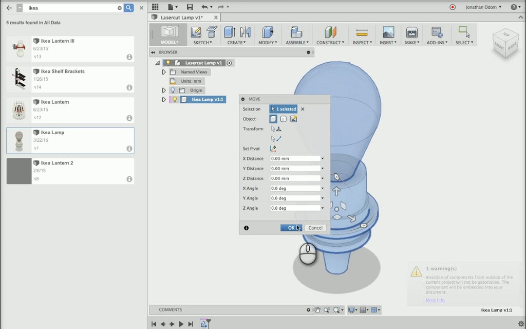
We want to move the light up a bit so that there will be room underneath the lamp for the cord to bend. Right-click on the component in the Browser, then drag the Up arrow on the Manipulator. 3" from the bottom looks like it will give us enough room to manage the cord. Click "OK" to finish the command.

Move cord set up by 3" (76mm)
Step 3: Create Profile Sketch
With the cord set in place, it's time to draw the side profile of the lamp. The lamp is going to be radially symmetrical, meaning when you rotate it on its axis it always looks the same. This means that in order to figure out the shape, all we need to do is draw one side of the profile and rotate it.
First, click Front on the Navigation Cube to get a view of the front plane of the model. Then click Create Sketch and select the XY Plane on the Origin. Fusion asks me if you want to "Capture the current position or continue in previous position"- click Capture Position because you need to keep the cord set model in the place you moved it.
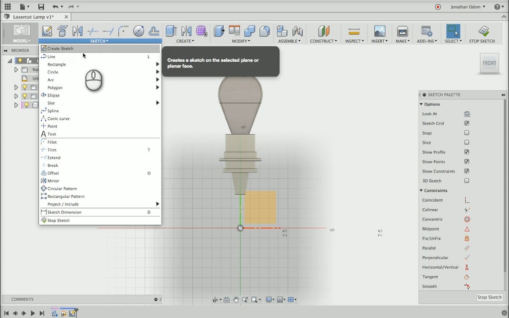
Create profile sketch
Go to Sketch>Line and draw a ground line from the origin, then Sketch>Project to project the profile of the cord set onto the sketch. The tool lets you switch between Specified Entities (faces, curves, points, etc.) and Bodies so that you can project exactly what you want. These lines will help you draw the exact profile you want in relation to the screw-on part of the cord set.
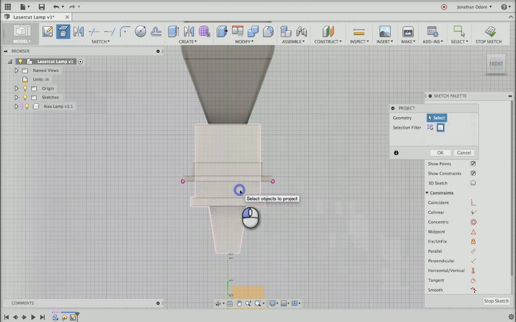
Project socket profile
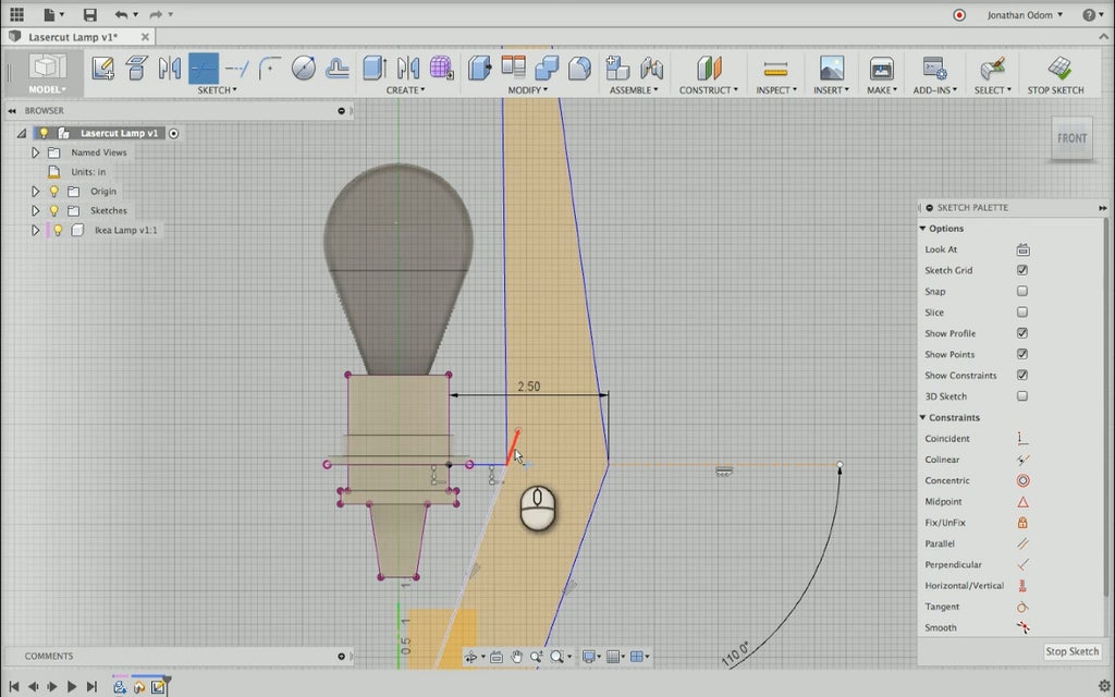
Draw another Line from the edge of the cord set and type "2.5" to give yourself a line that's 2 1/2" (64mm) from the edge. Keep drawing lines to give yourself a profile that looks good to you. The shape possibilities are pretty much endless, so I would encourage you to play around with the Sketch menu and see what you can come up with.
All we're trying to do here is make a fin that's wide enough to shade some of the direct light from the bulb while not getting too close to it.
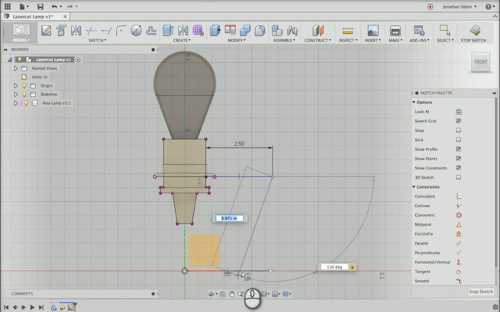
Draw fin
Adjust the lines a little make more space between the bulb and the fin if necessary, then get rid of the lines using Sketch>Trim. Stop Sketch gets you back to the modeling environment.
Trim to create closed profile
Step 4: Create Fin and Ring
Now that the profile is finished you can create your fin component. Go to Create > Extrude and select the profile you just created. Type in .23" (5.8mm), which is the actual thickness of the 1/4" plywood. When you hit the Enter key, you get a new Body under the Bodies folder in the Browser. Select the body, right-click, and select Create New Component then re-name the new component "Fin" to help keep track of the parts in the design.

Extrude fin from sketch
Next, we need to create the ring component that the cord set will attach to. Go to Sketch > Create Sketch and select the underside of the nut part of the cord set as my sketch plane. Draw a Circle from the Sketch menu and type "5" to give it a 5" (127mm) diameter.

Create sketch for ring part
Click Stop Sketch and go to Create > Extrude to create the rim component. The sketch you created should have 2 profiles, so select them both for a complete profile. Use the .23" dimension again for the extrusion Distance. By default, the Operation is Cut, meaning it's going to cut through any geometry that crosses it. You shouldn't cut anything just yet, so set the Operation to New Component. After clicking OK, rename the component to help keep things tidy. You can click the Show/Hide icons on each of the model components to see what you've got.

Extrude sketch to create ring
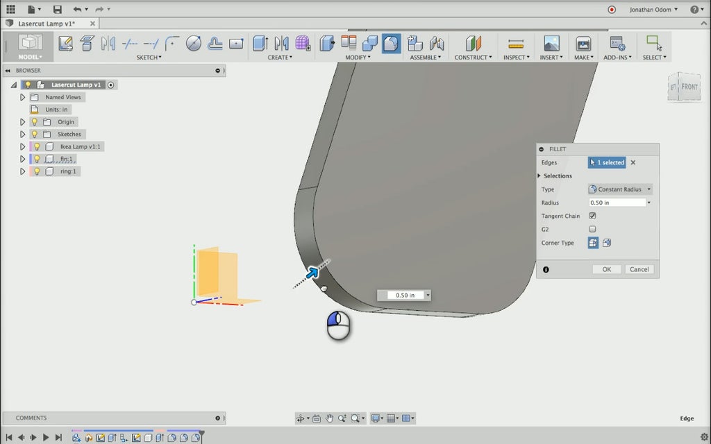
Step 5: Refine Fin Shape
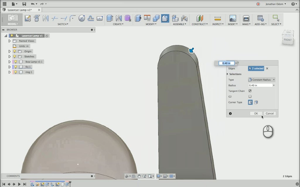
If you want to give my fin a more elegant profile, use the Fillet tool now and smooth it out. Go to Create > Fillet and select the edges you want to round out. You can drag the arrow and eyeball the curves in order to get a shape that looks good to you.
Step 6: Create Fin Array
Right now, the fin is perpendicular to the side of the cord set. The piece will look better is the fins are angled towards the lightbulb so that they slightly obscure it. To do this, right-click on the Fin component in the Browser, select Move, and rotate the Y-axis until the angle looks good to you.

Rotate fin in place
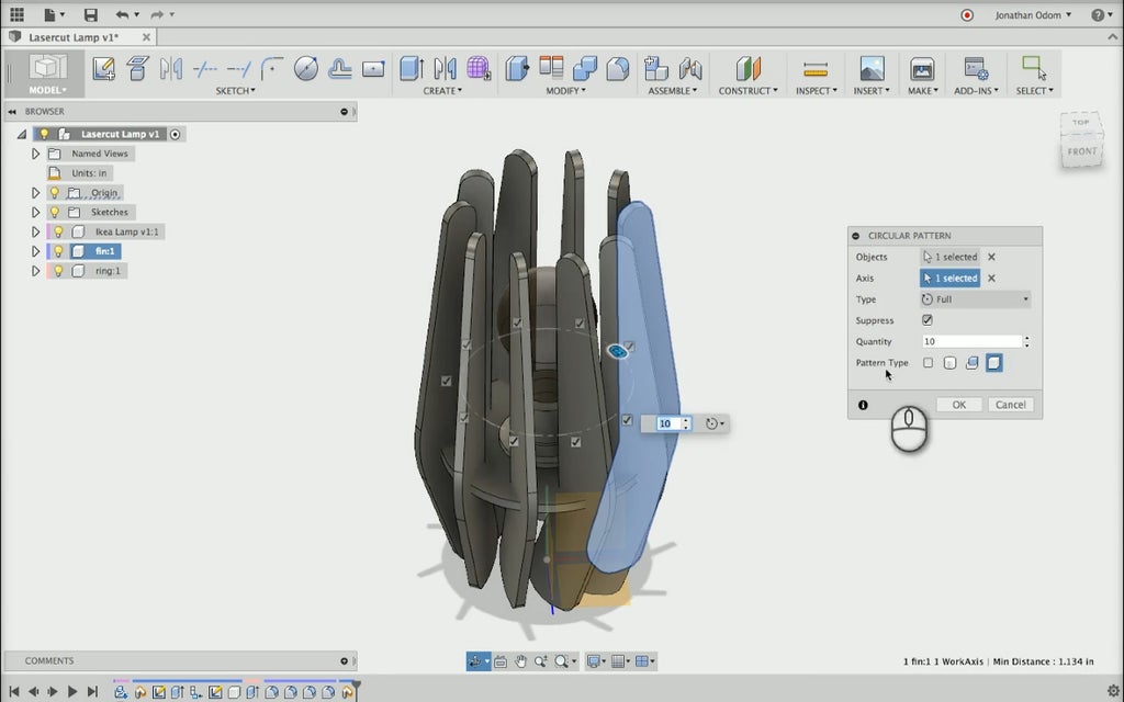
Now that the fin has the right orientation, we'll create multiple copies of it rotated around the center axis of the design. Go to Create > Pattern > Circular Pattern. You'll get that "Capture the current position or continue in previous position?" warning again– click Capture Position because you need to keep the new orientation of the fin. Select the fin, then make sure Pattern Type is set to Pattern Components.
Next, click Select Axis and click on the green Y-Axis on the Model Origin. The default Quantity of components is 3, so you'll need to increase that number until it looks like right to you. We need the right balance between exposure and cover of the light bulb, and 10 looks like a pretty good number.
Create array of fins around Y axis
Step 7: Create Interlocking Cuts
Now that we've got all my components in place, it's time to make the interlocking features. These will work pretty much the same way they did in the Smart Phone Stand project.
Go to Sketch > Create Sketch and select the face of one of the fin components. Next, go to Sketch > Project and select the ring body to project the side profile of the ring onto the sketch. Draw a new Line from the end of the ring the end of the fin on the inside, then draw a perpendicular Line from the midpoint (the point where the blue triangle snaps). This will give me a cut that stops half way between the intersection of the fin and the ring.

Project ring profile from body
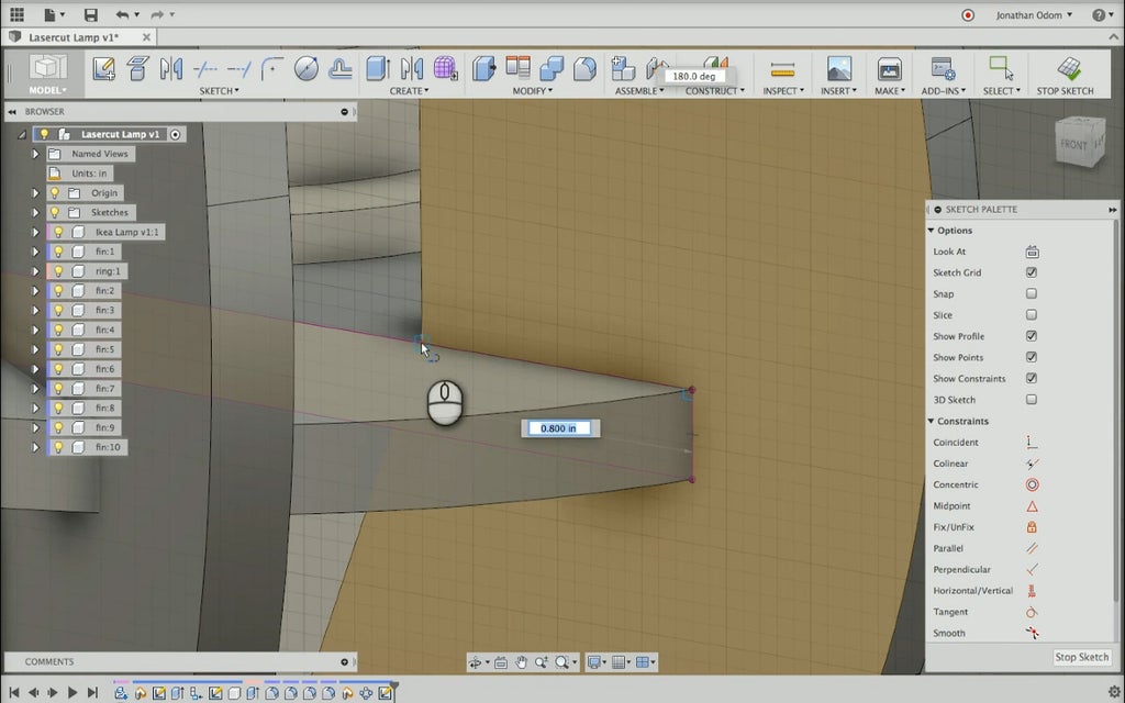
Draw new line to create midpoint
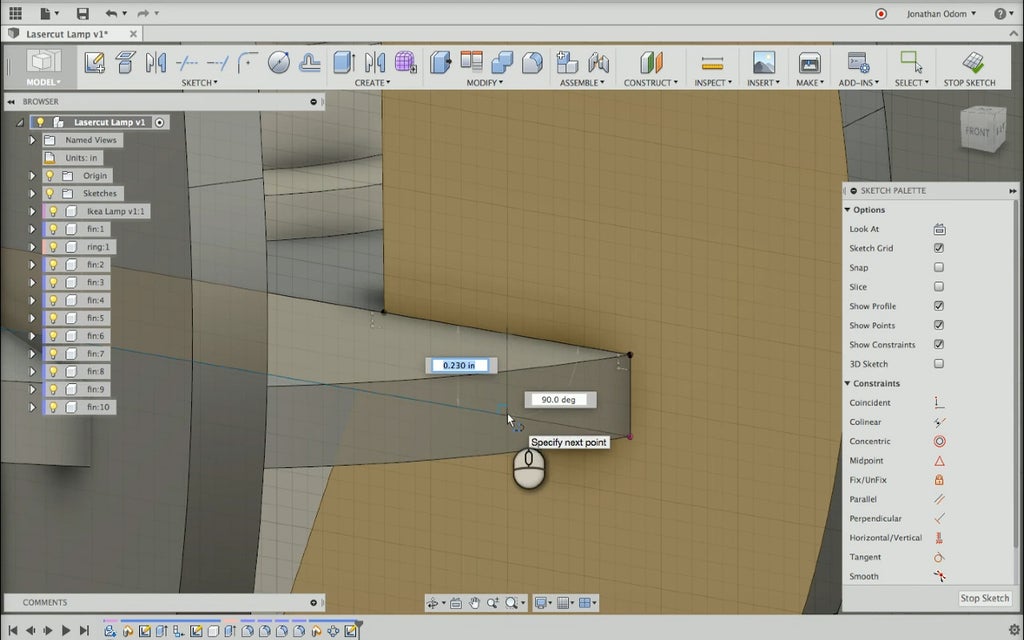
Draw line at midpoint of intersection
Go to the fin you just sketched in the Browser, right-click, and select Isolate in the popup menu so you can create the cut without other pieces getting in the way. You'll have to go to the Sketch Folder in the Browser and turn on the sketch you just created. Then go to Create > Extrude and extrude the inside profile you just made so that it cuts all the way through the fin.

Extrude cut for interlock
When you did the Circular Pattern in the previous step, you chose Pattern Components for the operation. This means that all of the fins are copies of one another. When you alter one (like you did with the extrusion cut you just made), all of the fins are altered. This saves a lot of time!
Now that the fins have their cuts, you need to make the interlocking cuts in the ring component. The easiest way to do this is to use the Combine tool. Go to Modify > Combine and select the ring as my Target Body. Click on Tool Bodies and select all of the fins in one selection since you're cutting all of these profiles out of the ring. The Operation has to be set to Cut, and you have to make sure Keep Tools is checked. If this box isn't checked, all of the fins will disappear.
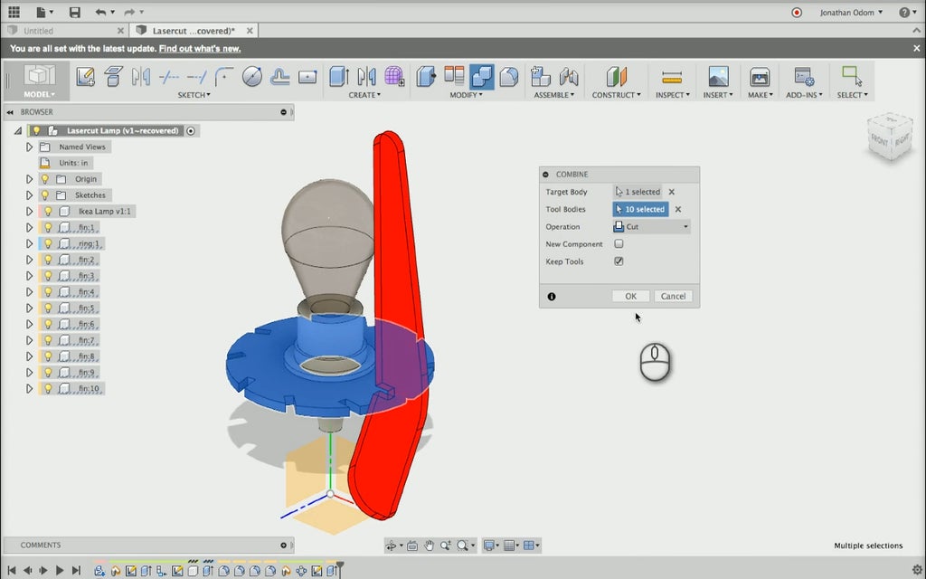
Combine with cut operation
Next we'll give the interlocks rounded edges– this will make the piece easy to assemble and prevent chipping on sharp corners. Isolate the ring component in the Browser, then go to Modify > Fillet and select all of the edges of the ring that were made from the Combine command. Drag the arrow to get a feel for how big the fillets should be– 0.10 in (2.5mm) looks like a good size. Isolate one of the fins and Fillet its interlocking edges too. Since all the fin components are copies, they all change as well.
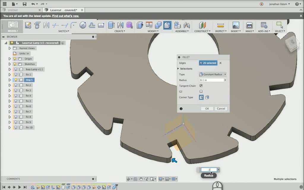
Fillet corners of ring
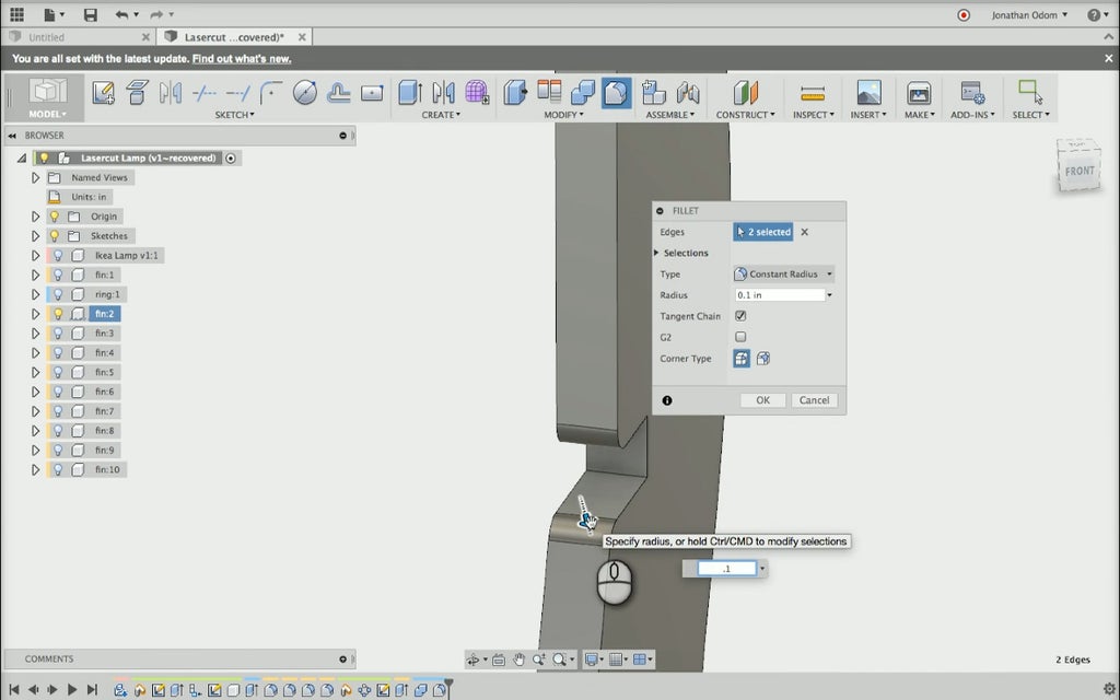
Fillet corners of fin component
Step 8: Create Panel Profiles
Now that my design is finished, we need to get the cut profiles out of Fusion and into Illustrator. Go to Sketch > Create Sketch and select one of the fin faces, then repeat this step on the ring component.
Right-click on these sketches in the Browser, then select Save As DXF so you can bring them into Illustrator.

Create new sketches from finished components
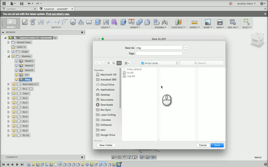
Save sketches to DXF format
Step 9: Create Illustrator Profiles
Create a new Illustrator document with 24"X36" dimensions (the size of the laser cutter bed). DXFs open natively in Illustrator, so you can open the ring and fin files and copy the lines into the new document.
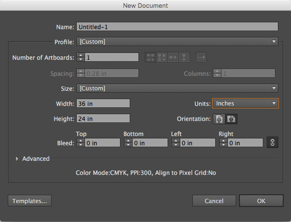
Create 36" X 24" illustrator document
Create 10 copies of the fin by clicking on the object and alt+dragging them using the default Select tool. It's best to keep all of the components to the left side of the layout and packing them close together to avoid wasting any unnecessary material. As before, select all of the lines and change the Stroke Weight to .001.
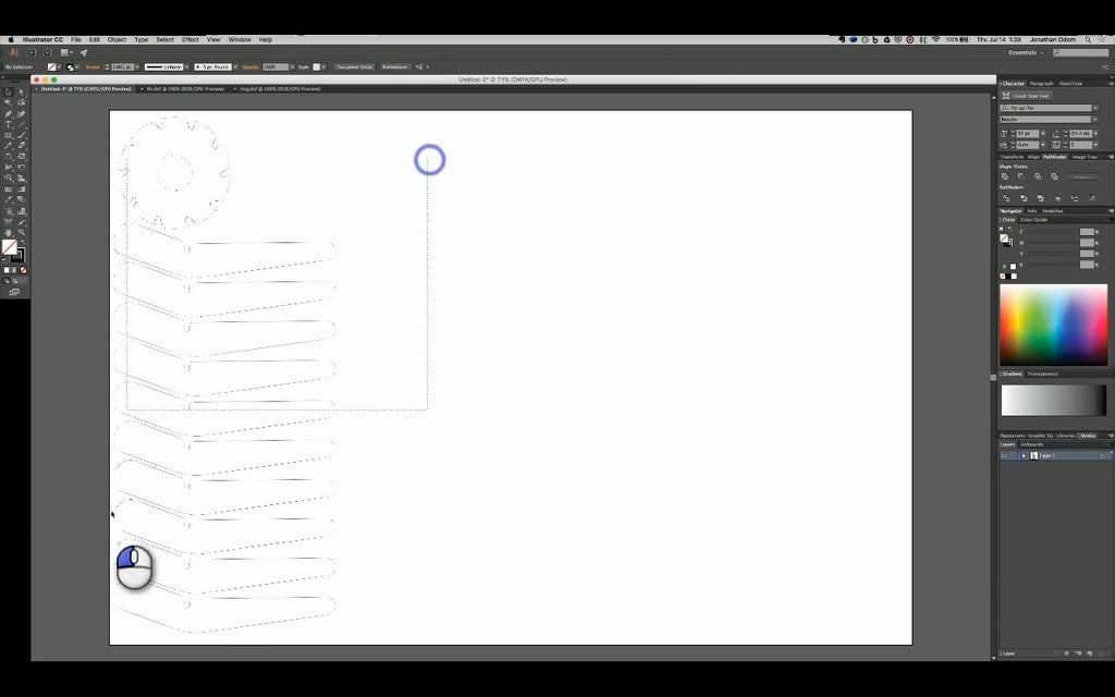
Copy and paste profiles for laser cutting
Step 10: Laser Cutting
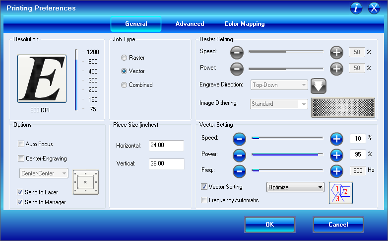
Since we're using 1/4" (6mm) plywood, we'll use the same settings that worked for the Smart Phone Stand.
- Job Type: Vector
- Piece Size: 36"X24"
- Speed: 10%
- Power: 95%
- Freq.: 500Hz
Remember to mask your material any time you're cutting. This is especially important in a project like this where all sides will be visible.
Step 11: Finished Product
Assembly for this project is super simple. With the exact material thickness dialed into the design, the fins should press-fit into place.
I've attached a PDF layout and an F3D Fusion 360 archive file here for your use.


