

Introduction: 3D Machining


Functions
![]() Machine Relief - Create a 3D toolpath that follows the contour of the 3D relief. The Machine Relief toolpath also allows for Z level roughing within the toolpath
Machine Relief - Create a 3D toolpath that follows the contour of the 3D relief. The Machine Relief toolpath also allows for Z level roughing within the toolpath
Step 1: Example 7-1

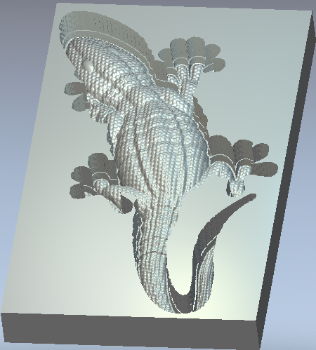
Step 2: Lizard Machining Tutorial
For this project we will machine the finished lizard into a soft material such as HDU. The lizard will then be cut out of the material. We will start by using a Machine Relief toolpath within a selected vector area so as to avoid machining the flat background which in this case we do not need. The lizard will be then cut out of the material using a Profile toolpath. We would like the finished lizard to have total height of 1.5”, but the lizard relief is currently 1.545”, so the lizard must first be scaled down in the Z prior to machining.
Preparing the Lizard for Machining
1 Open the file Lizard.art
The relief must be scaled down in the Z only.
2 Open Scale Relief Height![]() from the Relief Editing Toolbar
from the Relief Editing Toolbar
- Scaling = Height
- Mask = None
- New Height to 35mm (1.5”)
- Detail = None
- Click the Apply button
3 Create a New Vector Layer called Machining
4 Hide the Default layer
5 Toggle on Preview Relief in the 2D view ![]()
For the 3D toolpath, we will machine within a vector boundary. When generating a Machine Relief toolpath within a specific area, it is good practice to offset the vector outwards by a little more than the radius of the tool you will use to cut it. The reason being, that during a Machine Relief toolpath, the center of the tool stops on the vector. Since the vector is right up against the relief, the tool cannot drop down to reach the bottom edge of the relief. If we offset the machining vector by the radius of the tool, there will be enough room for the tool to reach down to the base of the relief. However in the Machine Relief we can have ArtCAM create a machining vector for us containing the correct offset (radius of tool) for the required cutting tool. The Automatic Boundary option will automate this whole process.
Machining the Lizard
1 Open the Machine Relief toolpath strategy ![]()
- Select the Automatic Boundary function
- Offset = 0
- Finish Tool = 3mm ball nose (1/8 Inch ball nose)
- Rough Tool = 6mm end mill (1/4 Inch end mill)
- Stepdown= 13mm (0.5”)


2 … continue Machine Relief Toolpath:
- Material
- Thickness = 50mm (2”)
- Material Z Zero= top
- Bottom Offset = 8mm (0.3”)

We are leaving 0.3” (8 mm) of stock material underneath the lizard, this will help strengthen the finished part.
3 3D View
4 Click the Calculate Now button
5 Close
6 Simulate Toolpaths![]()

7 2D View
8 Open the Create Vector Boundary tool ![]()
- Create a vector boundary around the Composite Relief
The vector we have just created follows along the outside edge of the lizard. This vector will be used for the Profile cut out pass, the last toolpath we will create. When a Profile pass is created, you have the choice to run the tool on the inside or the outside of the vector. In this case, we will choose the outside.
9 Select the new boundary vector on the edge of the lizard
10 Open the Profiling toolpath function ![]()
- Finish Depth = 50mm (2”)
- Tool = 3mm end mill (1/8 Inch)
- Stepdown = 13mm (0.5”)
11 Click the Calculate Now button
12 Click the Close button
13 3D View
14 Choose the Profiling toolpath
15 Simulate Toolpath![]()

The toolpaths are now ready to be sent to the router to be machined.


