

Introduction: Flat Pack Design Preparation


The table model provided here is designed so that all the pieces will fit within a standard 4'X8' sheet of plywood. The first step in the CAM process will be to make copies of all the pieces and place them in a layout that will fit on the bed. For this lesson, you can either use the model provided or use the one you designed in the Table Design lesson.

caption
Step 1: Table Model
If you skipped the table design lesson, I've provided the attached table model as an example you can use to follow along with the CAM process.
FLAT PACK / FRICTION FIT
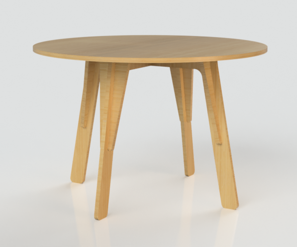
This table is designed to be flat packed and friction fit. Flat pack refers to its being made of interlocking flat parts, and friction fit means it can be assembled so that the friction between the pieces will hold it together without any fasteners.
The table has 7 parts in total. Two legs, four stiffeners, and one table top. The stiffeners provide lateral stability to keep the table from twisting or wobbling.

PARAMETRIC THICKNESS
This model has also been designed using a parametric thickness. In 3D modeling, parametric means that a variable has been established that can be changed later, automatically changing any part of the model that used the parameter.

This model has a single parameter called "t" which is set to a value of .76 in. The cutouts for the interlocking parts and the pockets were all created using this parameter, so if you change this value to anything between about .7 in and .8 in, it should update everything without any problems.
To learn more about the concept, go back to **Lesson 5
UPLOAD THE MODEL
1. Download the F3D file attached here.
2. Open Fusion, open the Data Panel by clicking the Grid icon on the upper left.
3. Click the New Project button and create a project with a unique name.

4. Click the Upload button at the top of the Data Panel.

5. Drag the table file you previously downloaded into the window and click Upload. The table design will now be in the cloud along with all your other Fusion files.

Attachments

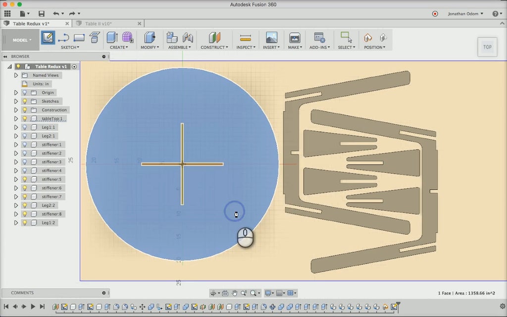
Step 2: Create Part Layout
In Fusion 360 you can create a CAM setup on any object in the model. That is to say if you wanted to, you could create a bunch of separate toolpaths on all the parts and run them separately on a CNC machine. This isn't really efficient for a project like the table. If you were to run a bunch of separate files, you'd have to set set the X and Y origin of each part which would waste time and probably material.
The best way to limit the amount of material wasted and save time is to make copies of the parts and align them all to the floor of the model environment. That way, you can run only two toolpaths (one pocket and one contour) and ensure that your parts will fit on the bed without too much wasted material. Follow these steps and you'll be ready to make your toolpaths.
CREATE A SHEET BOUNDARY: To make sure your parts will fit on the bed, first sketch a sheet boundary.
- Go to SKETCH > Create Sketch, then click on the "floor" plane of the model space on the origin. If you get a "Some components have been moved" warning, be sure to click Capture Position.
- Next, go to SKETCH > Rectangle and click the model origin. My sheet is 48" X 96", so I type "48" in the first field, hit TAB, then type "96" in the next field.
- Hit ENTER to leave the rectangle tool, then click Stop Sketch on the toolbar to leave the sketch environment.

CREATE COPIES OF PARTS: To create the part layout, you'll need to make copies of the parts. This is a preferable to just moving the parts that are already in the model because you might want to change your design later, and the best way to do that is usually to do it while the table is assembled. If you change one copy of a component, all other copies will automatically update.
- Select all the components in the Browser, right-click > Copy, then right-click > Paste.
- Turn off the original components by clicking the Lightbulb next to each one in the Browser.

ALIGN PARTS TO SHEET SKETCH: It's very important to make sure that all the parts are aligned to the same plane. If they aren't you can get all kinds of problems down the road when you're creating your CAM setup.
- Go to MODIFY > Align, click on the tabletop, then click on the sketch. The pockets need to face up, so you may need to click the Flip icon to flip the table the right way.
- Repeat this step on every part of the table, ensuring that they're all flipped as necessary so that they are all aligned to the same plane.

Step 3: Nesting
In order to ensure that the parts have ample space between them for the tool to cut, and that the minimum amount of material is wasted, you'll now do what's called "nesting".
- Click the TOP face on the View Cube in the upper right corner. Next, click-and-drag the parts around to get a general layout that looks reasonable.
- To rotate, right-click on any part in the Browser and select MOVE from the drop-down menu. Click-and-drag the arcs to rotate the parts, and click-and-drag the square to move the parts in 2 dimensions.
- Make sure the manipulator is aligned with the XYZ axes of the model before rotating. The stiffeners in my model have a weird orientation because they were made in a plane that wasn't squared to the world origin. To fix this, click the Set Pivot icon, click anywhere on the part's top face, then click the green checkbox in the MOVE window.You will now have a properly aligned manipulator that you can use to rotate.
- Once the parts have the right rotation, move them around so that you don't waste too much material, but leave about 1" between the parts to give the tool some space to move around.

Step 4: Corner Treatment
INSIDE VS. OUTSIDE CORNERS
Corners have one simple rule in CNC: Outside corners can be sharp, inside corners must be rounded. Since a round end mill is doing the cutting, the radius of any inside corner will always match the radius of the end mill. Sharp outside corners are easy, but there's no way to get sharp inside corners with an end mill on a 3-Axis CNC.

Because of this universal fact, you cannot leave rectangular geometry as-is after designing a flat pack object and fit the parts together as desired.

Of course, you could always chisel out the corners or use a file, but if you want to quickly and cleanly assemble the project, there are a few tricks listed below.
OUTSIDE FILLETS
This corner treatment allows for a flush connection between the parts because the end mill travels outside the corner by a distance that's equal to the radius of the bit, allowing the end of each cut to sit flush against the other. This kind of joint works well structurally speaking, but the fillet is visible after the parts are assembled.

INSIDE FILLETS
This corner treatment allows for a flush connection between the parts because the end mill travels outside the corner by a distance that's equal to the radius of the bit, allowing the end of each cut to sit flush against the other. The difference is that the fillet is cut into the short end of the cut. This kind of joint works well structurally speaking and is invisible once the parts are assembled.
Inside fillets can be a bad idea if the material is too thin as compared to the end mill. For example, if you were to use a 5/16" end mill with a 3/4" piece of plywood, this type of fillet would leave you with a 1/8" flat spot on the inside of the corner, which would probably just get broken off with soft plywood.

DOGBONE FILLETS
This corner treatment allows for a flush connection between the parts because the end mill travels outside the corner at an angle so that the cut is made equally on each leg of the cutout. Let material is cut with this method, it can be done automatically using a script, and the fillet is less conspicuous than an outside fillet would be. I pretty much exclusively use inside fillets because they're invisible, but doing doggone fillets with a script is definitely a time saver.
Here's a link to a Fusion 360 add-in complete with installation instructions if you want to go this route: https://github.com/caseycrogers/Dogbone

Step 5: Create Fillets
For this project, inside fillets are the best choice. With 3/4" piece of plywood and a 1/4" end mill, there will be a 1/4" wide flat spot at the end of each cut, which will be fine for our purposes. Here are the steps:
CREATE A SKETCH: Go to SKETCH > Create Sketch and click on the the side of the table top that's facing up in the model.
DRAW CIRCLES: Zoom in on the rectangular ends of the pocket, go to SKETCH > Circle > 2-Point Circle, click one of the points on the rectangular end, then hover over the other point on the rectangular end- this will ensure that the circle is aligned properly. Type the diameter of the tool (.25), then hit ENTER. This will create a circle with a .25" diameter that's attached to the side of the pocket. Repeat this step on every inside corner of the pocket.
- NOTE: Do not pattern or copy / paste these circles to save time. The circles need to be constrained to the ends of the pockets to allow for changing the overall thickness of the material later if necessary.
- NOTE: The diameter of the fillets will depend on your end mill. Make sure you're using the right number here!

EXTRUDE FILLETS: Click on Stop Sketch, then go to CREATE > Extrude. Select the profile made by each circle, then for the extrusion distance type "-t/2".
- "t" is the thickness parameter that was used to set the thickness of all the parts. The thickness parameter is set to 0.76 in, so t/2 = .38 in.

TEST THICKNESS PARAMETER: To ensure that the fillets are properly constrained to all the corners, change the parameter thickness and take a look at the fillets. Go to MODIFY > Change Parameters and double-click on the number under Expression in the User Parameter "t". Change this to something noticeably bigger like 1 in.If the fillets were drawn properly in the sketch, they should still be aligned to the ends of each of the pocket's inside corners, and the depth of the pocket should now be .5 in with the fillets going all the way to the floor of the pocket. Undo and Redo this change a couple of times to see the thickness change.
Parameters are crucial to flat pack projects like this because plywood comes in so many different thicknesses. It's almost never .75" when it's nominally called 3/4" plywood, and one batch will often differ from the last even from the same supplier.

REPEAT AS REQUIRED: All of the inside corners of the design are going to need fillets in order for the table to fit together without any gaps. Repeat these steps on the rest of the parts and use the "t" parameter to ensure that all of the fillets will have full depth when parameters change
Finally, go to the Browser, hide the copies of the table parts that are flat on the floor, and show the components for the assembled table. Look around at the joints to make sure none of the fillets are showing up.
Step 6: Recap
In this lesson, you learned how to create nested layouts of flat pack parts to minimize material waste and save time. You learned how to manually create filleted corners that are controlled by parameters, and you got a link to a plugin that can create doggone fillets automatically.


