

Introduction: Relief Creation


Functions
![]() Shape Editor - Emboss a basic 3D relief from a vector or image
Shape Editor - Emboss a basic 3D relief from a vector or image
![]() Preview Relief Layer - interactive golden greyscale representing active relief
Preview Relief Layer - interactive golden greyscale representing active relief
![]() Reset Relief - Reset all heights in relief back to zero
Reset Relief - Reset all heights in relief back to zero
![]() Draw Zero Plane - Toggle switch to show and hide the zero plane in 3D view
Draw Zero Plane - Toggle switch to show and hide the zero plane in 3D view
![]() Origin - A toggle switch to show and hide the origin in the 3D view
Origin - A toggle switch to show and hide the origin in the 3D view
![]() Paste Relief From A File - Load a previously saved relief from disk (.rlf)
Paste Relief From A File - Load a previously saved relief from disk (.rlf)
![]() Save Relief - Save a relief to disk (.rlf)
Save Relief - Save a relief to disk (.rlf)
![]() Relief Clipart Library - Customisable library installed with over 400 3D reliefs
Relief Clipart Library - Customisable library installed with over 400 3D reliefs
![]() Extrude - Extrude a vector cross section(s) along drive curve to create a relief
Extrude - Extrude a vector cross section(s) along drive curve to create a relief
![]() Two Rail Sweep - Sweep a vector cross section(s) between two drive rails to create a relief
Two Rail Sweep - Sweep a vector cross section(s) between two drive rails to create a relief
![]() Create Vector Boundary - Automatically creates a vector around the outside edge the relief
Create Vector Boundary - Automatically creates a vector around the outside edge the relief
![]() Display Material - show the shaded material (default gold) in 3D view
Display Material - show the shaded material (default gold) in 3D view
![]() Display Bitmap - show colours from 2D view on 3D view
Display Bitmap - show colours from 2D view on 3D view
![]() Toggle Vector Visibility - Hide and show vectors in the 3D View
Toggle Vector Visibility - Hide and show vectors in the 3D View
Note, some functions are grouped together in Toolset shown by the small arrow the in lower right corner of the function. Hold the mouse down on the icon and continue to hold to pull out the menu.
Step 1: Example 5-1

Step 2: Anchor Relief Tutorial
This example shows how to create and work with basic relief shapes.
1 Click on the Open Model function in the Start Panel to display the Open dialog box
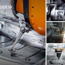
2 Open the model anchor.art

The vectors are displayed in the 2D view and 3D View.
This tutorial is based in the default ArtCAM function layout. If you have customised your layout and wish to return to the default, from the Window pull down menu choose Reset Layout>Standard
3 Change the 3D View from Top View to Isometric View ![]()
The vectors are displayed on the 3D View.
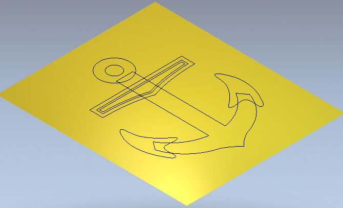
4 Double left mouse click on the vector shown below to open the Shape Editor form
5 Select a Plane shape with a Start Height of 0.5 mm(0.02”)

For a Plane, The Start Height indicates the very top Z level.
6 Set the Combine Mode to Add
7 Click the Apply button to generate the shape
8 Click the Cancel button
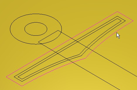
9 From the 3D view toolbar, click on Draw Zero Plane![]() to hide the Z zero plane
to hide the Z zero plane
The bar is produced as shown. If you place the mouse on the Relief, the Z height at that point 0.5mm (0.02”) will be displayed in the information box at the lower right of the graphics area.
![]()
10 De-select the bar vector by clicking in empty space
11 Hold down the shift key and select the two inner vectors as shown

A Relief will now be generated inside the two selected vectors.
12 Press F12 on the keyboard to open the Shape Editor form
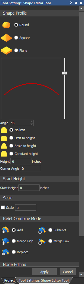
13 Select a Round shape with an Angle of 45 degrees and No Limit with regard to overall height
14 Enter a Start Height value of 0(0”)
15 Click the Apply Button
16 Click the Cancel button

A Dome shape of 45 degrees has been created within the selected vectors. The final height of the dome was dictated by the defined angle (as No limit was selected)
By Selecting Add, the new relief ‘added’ to the initial bar relief below.
The main body of the Anchor will now be created and merged into the current Relief.
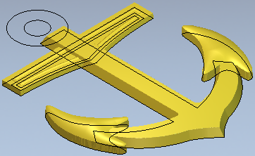
17 Select the main anchor vector as shown highlighted

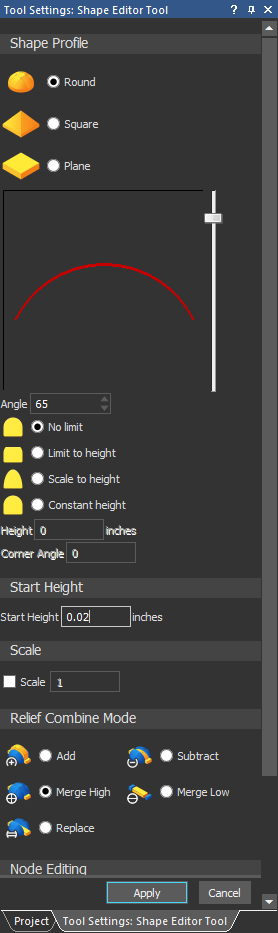
18 Press F12 on the keyboard to open the Shape Editor form

19 Select a Square shape with an Angle of 65 degrees
20 Select Limit to Height and Enter a value of 0.75mm (0.03”)
21 Click the Merge High box and Apply
22 Click the Cancel button

The main anchor shape is created and merged with the bar relief.
This shape was produced from the vectors extruding as a triangular shape of 65 degrees. As it reached a height of 0.65mm, it ‘levelled off’.
23 Shift Select the two hook vectors as shown

24 Press F12 on the keyboard to open the Shape Editor form

25 Select a Round shape with an Angle of 30 degrees
26 Enter a Start Height value of 0.75mm (0.03”)
27 Click the Merge High box and Apply
28 Click the Cancel button
The ‘hook shapes’ have been created and merged with the main body.
The Start Height provided a ‘platform’ of 0.75mm before a dome shape of 30 degrees was applied.
29 Shift Select the two Circle vectors as shown

30 Press F12 on the keyboard to open the Shape Editor form
31 Select a Round shape with an Angle of 65 degrees.
32 Enter a Start Height value of 0.5 mm (0.02”)
33 Click on Merge High box and Apply
34 Click the Cancel button
35 From the 3D View toolbar, click on Toggle Vector Visibility![]()

The Vectors are hidden, and the final result can be seen clearly.
36 Save the ArtCAM Model
Attachments
Step 3: Bitmap Motif Tutorial
The following tutorials demonstrate the creation of a basic relief from bitmap colors.
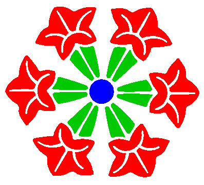
1 Open BitmapMotif.art
2 Switch to 3D View
3 Toggle on Display Bitmap icon from the 3D View toolbar ![]()

4 Double click on the colour blue directly to open the Shape Editor
- Choose a Round shape with an angle of 30 degrees
- Enter in a Start Height of 1mm(0.05”)
- Check Scale To Height and type in a Height of 3.5mm(0.15”)
- Click Apply and Cancel
5 Double click on the colour green to open the Shape Editor
- Choose a Round shape with an angle of 30 degrees
- Enter in a Start Height of 1.5mm(0.1”)
- Click Apply and Cancel

6 Double click on the colour red to open the Shape Editor
- Choose a Round shape with an angle of 40 degrees
- Enter in a Start Height of 2mm(0.1”)
- Check Limit To Height and type in a Height of 2mm(0.1”)
- Click Apply and Cancel
7 Select Display Material![]() to toggle back to the Relief (material) view.
to toggle back to the Relief (material) view.
8 Select Smooth Relief![]() from the Relief Editing Toolbar
from the Relief Editing Toolbar
- Apply 3 smoothing passes and close the form
9 Toggle Zero plane![]() from the 3D view Toolbar to view the results.
from the 3D view Toolbar to view the results.


