

Introduction: Slouch Alert Circuit


In this lesson, you will clip the final Slouch Alert circuit together and upload the final sketch. The circuit uses the concepts you learned during both the Analog Input and Analog Output lessons. This project notifies you when you are slouching with a little vibration via the vibe motor. This project also uses the snap switch from Introducing the Switch lesson as an on/off switch.
As an added bonus, after you build the Slouch Alert, I will teach you how to turn your body into a musical instrument using this same circuit and the very easy to use Soundplant software.
At this point, the sensor should be off the t-shirt. The hook side of the Velcro stays on the t-shirt, holding the sensor's place so you know where to put it when you build the circuit on the t-shirt.
Step 1: Materials

Download the final sketch.
+ microcontroller
+ USB cord
+ alligator leads
+ vibe board
+ snap switch
+ handmade flex sensor
+ resistor for voltage divider circuit
+ paper
+ pen
Attachments

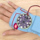
Step 2: Build Circuit

Connect the circuit as illustrated.
flex sensor --> power (+)
flex sensor --> resistor
resistor (same side the flex is connected to) --> pin A5
resistor --> ground (-)
snap switch --> pin 2
snap switch (-) --> ground (-)
vibe board power (+) --> pin 11
vibe board ground (-) --> ground (-)

There will be three clips connected to the ground (-) pin. In the Analog Output lesson, you used half of the snap switch to break it out to make it easier to clip to. Three is the max amount you can get on there so you do not necessarily need it now. However, since you are using the switch for this project you may want to make yourself another one for future use!
Step 3: Upload

Open the previously downloaded sketch, upload it to your board and open the serial monitor.

Let's test to see if the circuit is connected correctly and working. Snap the switch closed. The values coming from your flex sensor should start streaming to the monitor.
If the sensor is more than 400 "slouch" will be printed in the monitor and the vibe motor will go on.

How Does it Work?
When the sketch loads and is running it reads the pin the switch is on to see if it's closed or open. When it is closed it reads the sensor values and when the sensor goes past a threshold it knows that you are slouching and turns the vibe motor on to indicate that you should straighten up!
Step 4: The Code
All of the code in the sketch is stuff you have used in the previous Arduino lessons. The only new lines are the ones that are created in the if() statement.
In this if() statement we are saying that if the average of the sensor readings go above 400, print "slouch" in the serial monitor and turn the vibe board on. Else, if the board is below 400, turn the board off. if (average > 400) {
Serial.println("slouch");
digitalWrite(vibeBoard, HIGH);
delay(1); // delay in between reads for stability
} else {
digitalWrite(vibeBoard, LOW);
}
}
400 is the threshold and can be changed anytime if you feel like the threshold is too high or too low. We will go over how to calibrate the sensor once you can wear it. The best way to calibrate is when the sensor is being used as it is supposed to be. The values it gives you now will be different than when you put it on the body to wear it.
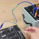
Step 5: Making It Mobile
The circuit is not ready to be untethered quite yet. This is because you still need to be able to read the sensor values coming from the board through the serial connection the board has with your computer via the USB cord. You still have calibration to do and since the board is powered by the USB cord you do not need the battery while it's connected.
Test With Battery
However, it is still a good idea to test the circuit with the battery. Go ahead and turn the board off and unplug the USB cord. Grab the battery and plug it in. Turn the board back on and wait about 30 seconds. Bend the sensor and feel the vibe motor go on. When you feel it that means it has crossed that threshold of 400. Even though you can not see the values you still know it's crossing that line.
Step 6: Record Connections

Record your circuit connections the same way you did for the Hi-5 Collector in the Hi-5 Collector Circuit lesson. As a refresher, here are the three ways to record a circuit.
1) Draw a schematic diagram.
2) Create your own drawing.
3) Write it down.
Double check the recording to make sure you wrote the connections down correctly. Share a photo of your diagram below!
Step 7: Disconnect

Once you have recorded the circuit, you are ready to safely take the circuit off the alligator leads. After you disconnect everything, you will have six components including the battery.
1 x LiPo battery
1 x LilyPad USB
1 x snap switch
1 x handmade flex sensor
1 x vibe board
1 x resistor
Share your final circuit clipped together and in action below along with your diagram. In the next step, we will be transferring this circuit to the t-shirt!


