

Introduction: Using Objet Studio


In this lesson you will learn how to prepare your model for printing using a program called Objet Studio.
Step 1: Use the Computer Closest to the Printer
Each printer is attached to two dedicated computers.
- The one on the desk closest to the printer is used to prepare the model and is referred to as the Design Computer.
- The one hidden in the printer enclosure controls the printer and is referred to as the On-board computer.
- The two computers share one keyboard, monitor and mouse using a KVM switch.
The program that prepares the model is Objet Studio.
- If Objet Studio is not on the computer you are using, use the KVM switch to access the software on the Design Computer.
Step 2: Insert (Open) the Model
- Open Objet Studio.
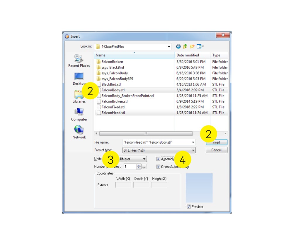
- Insert (open) your .STL file with the Insert button.
- Open more than one file by Control clicking.
- Select the units.
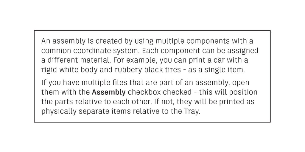
- Check the Assembly box if needed.
You’ll use commands under the three tabs to prepare the model and change settings.
- Tray Settings
- Model Settings
- Job Manager
Step 3: Tray Setup
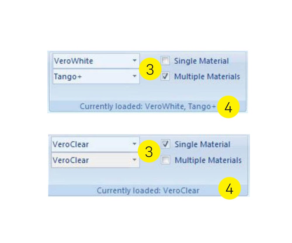
SET TRAY AND MATERIAL OPTIONS
Confirm that the materials loaded in the printer are accurately listed in the software.
- Click the Tray Settings tab. This ensures that the Model tab will
display the correct materials available.
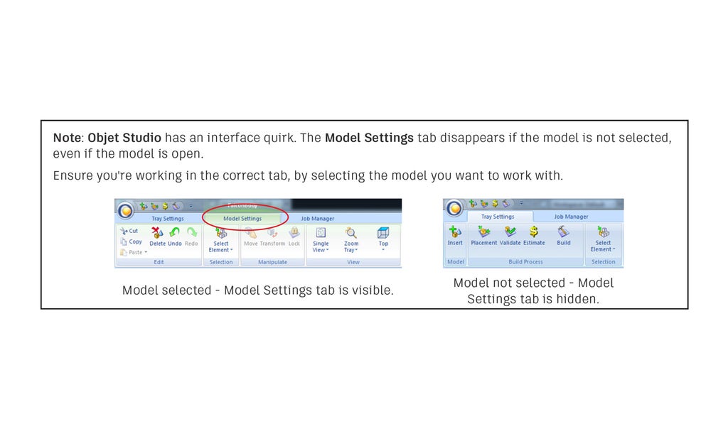
- Ensure that you are not in the Model Settings tab, which allows you to work with the two materials you selected in the Tray Settings tab.
- Confirm that the materials loaded in the printer are correctly
listed in the Currently Loaded toolbar.
- If not, select the correct materials from the menu.

- Confirm that the correct Single Material or Multiple Materials
button is checked.
- If the materials are exactly the same, check Single Material.
- If the materials are different in any way, check Multiple Materials.
- Double check that the materials list at the bottom of the Tray Settings tab matches your selection.

Model Placement
Objet Studio will place your part upon opening. Clicking the Placement button prompts suggestions for different placement and orientation options to create fast and lower cost printing.
- The Placement button is in the Tray Settings tab.

Model Manipulation
The Manipulate tools in the Model Settings tab are used to move, transform and lock the model.
- Move - drag the parts in the X or Y axis.
- Transform - rotate, move or scale by inputting values.
- Lock - fixes the part in place when using the Placement button.
Printing speed is related to orientation
- Z (height)
- Z is the slowest axis to print; when possible orient the part’s shortest dimension along the Z axis.
- X (right and left)
- The lines onscreen represent the approximate print area of a single pass of the print head.
- Contain the model in as few stripes as possible.
- X prints fastest, and should be parallel to the longest dimension of the print.
- Y (forward and back)
- When possible, Y should be longer than Z but shorter than X.
Step 4: Model Settings
THESE SETTINGS ALLOW YOU TO CHANGE HOW THE PART WILL BE PRINTED.
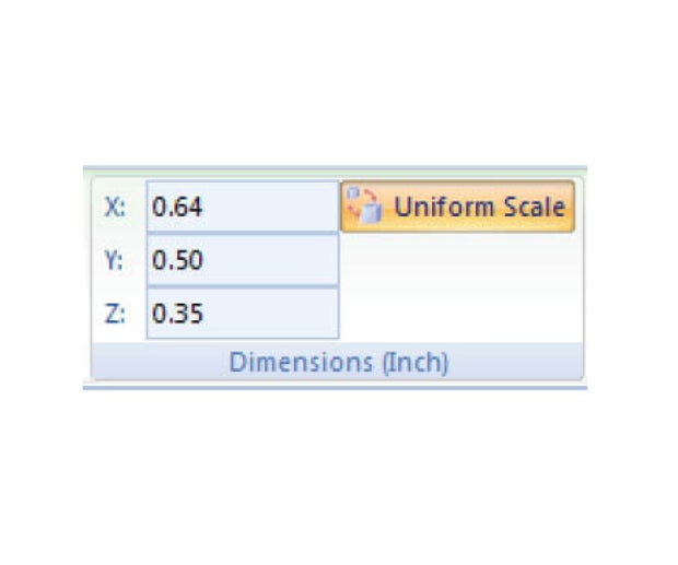
CHANGING MODEL DIMENSIONS
The dimensions tool allows you to scale the part or change X, Y or Z individually. Remember that scale is critical to time and cost of printing.
- Type a number to change the dimension of that axis.
- Deselect Uniform Scale to change an individual axis.
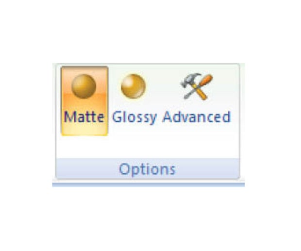
CHANGING MODEL SURFACE QUALITY
When the support material is removed, the build material under it will have a matte finish.
- Click Glossy to leave areas of the model uncoated, if they didn’t require
supports.
- Overhangs and the underside of the model will still require Support Material. There will also be a distinct boundary like the one that exists between the Glossy and the Matte areas.
- Click Matte to cover the entire part with a layer of support material,
which results in a uniform matte surface finish.
- These parts will be more dimensionally accurate than parts with a mixed surface finish.
CHANGING MODEL INTERIOR QUALITY
Changing the interior of the part can save money and change the weight of the part.
Click the Advanced button to show more options.
- Grid Style changes the overall density of the Support Material.
- Light support is best for delicate parts.
- Heavy support is best for large, heavy parts.
- Hollow saves money by filling the interior of your part with less
expensive support material and covering it with the more expensive
model material.
- Clear prints will show the support material if printed hollow.
SELECT THE MODEL MATERIAL
If the printer is loaded with multiple materials you can check the Model Settings menu for possible blends of the Model Materials.
- Hovering over a material combination displays more information.
Other options
- Coat with
- This will create a coating of one material over the model.
- For example, you could create a rigid ball with a squishy coating.
- Separate to Shells
- If you inserted (opened) an .STL file with multiple geometric bodies, this will break it into component parts.
- This option allows you to work with a single file, if it contains multiple bodies (the inverse of the Assembly option).


